Nuclear instrumentations are usually categorized as: Excore Nuclear Instrumentation and Incore Nuclear Instrumentation. Both systems are based on detection of neutrons. Radiation Dosimetry
In nuclear reactors, the thermal power produced by nuclear fissions is proportional to neutron flux level. Therefore, from reactor safety point of view, it is of the highest importance to measure and control the neutron flux and the spatial distribution of the neutron flux in the reactor correctly and by appropriate instrumentation. For this purpose, various nuclear instrumentations are installed. These measurements are usually performed outside the reactor core, but there are also measurements performed from inside the core. Therefore, nuclear instrumentations are usually categorized as:
Excore Nuclear Instrumentation. The neutron flux is usually measured by excore neutron detectors installed outside the core. These detectors belong to so called the excore nuclear instrumentation system (NIS). Since the neutron flux covers a wide range (about 12 decades), three ranges of instrumentation are used to obtain accurate flux level measurements:
Incore Nuclear Instrumentation. The incore nuclear instrumentation system measures neutron flux distribution and temperatures in the reactor core. The purposes of the incore instrumentation system are to provide detailed information on neutron flux distribution and fuel assembly outlet temperatures at selected core locations. The incore instrumentation system includes:
Both systems are based on detection of neutrons. The neutron flux is usually measured by excore neutron detectors installed outside the core. These detectors belong to so called the excore nuclear instrumentation system (NIS). The neutron flux and its distribution within the core is usually measure by an incore system, which is installed inside the reactor. Although the nuclear instrumentation system provides prompt response on neutron flux changes and it is irreplaceable system, it must be calibrated. The accurate thermal power of the reactor can be measured only by methods based on energy balance of primary circuit or energy balance of secondary circuit. These methods provide accurate reactor power, but these methods are insufficient for safety systems. Signal inputs to these calculations are, for example, the hot leg temperature or the flow rate through the feedwater system and these signals change very slowly with neutron power changes. In other word, the thermal power measured by calorimetrical methods is accurate, while the nuclear power measured by excore neutron detectors is the only system capable of fast reactivity excursion detection.
Reaction Rate – Proportionality between Neutron Flux and Thermal Power
Knowledge of the neutron flux(the total path length of all the neutrons in a cubic centimeter in a second) and the macroscopic cross sections (the probability of having an interaction per centimeter path length) allows us to compute the rate of interactions (e.g. rate of fission reactions). This reaction rate (the number of interactions taking place in that cubic centimeter in one second) is then given by multiplying them together:
To determine the thermal power, we have to focus on the fission reaction rate. For simplicity let assume that the fissionable material is uniformly distributed in the reactor. In this case, the macroscopic cross-sections are independent of position. Multiplying the fission reaction rate per unit volume (RR = Ф . Σ) by the total volume of the core (V) gives us the total number of reactions occurring in the reactor core per unit time. But we also know the amount of energy released per one fission reaction to be about 200 MeV/fission. Now, it is possible to determine the rate of energy release (power) due to the fission reaction. It is given by following equation:
P = RR . Er . V = Ф . Σf . Er . V = Ф . NU235 . σf235 . Er . V
where:
P – reactor power (MeV.s-1)
Ф – neutron flux (neutrons.cm-2.s-1)
σ – microscopic cross section (cm2)
N – atomic number density (atoms.cm-3)
Er – the average recoverable energy per fission (MeV / fission)
Robert Reed Burn, Introduction to Nuclear Reactor Operation, 1988.
U.S. Department of Energy, Nuclear Physics and Reactor Theory. DOE Fundamentals Handbook, Volume 1 and 2. January 1993.
Paul Reuss, Neutron Physics. EDP Sciences, 2008. ISBN: 978-2759800414.
See also:
Nuclear Reactor
We hope, this article, Nuclear Instrumentation, helps you. If so, give us a like in the sidebar. Main purpose of this website is to help the public to learn some interesting and important information about radiation and dosimeters.
In the bubble chamber, the tracks of subatomic particles are revealed as trails of bubbles in a liquid heated to just below its boiling point, usually liquid hydrogen. Radiation Dosimetry
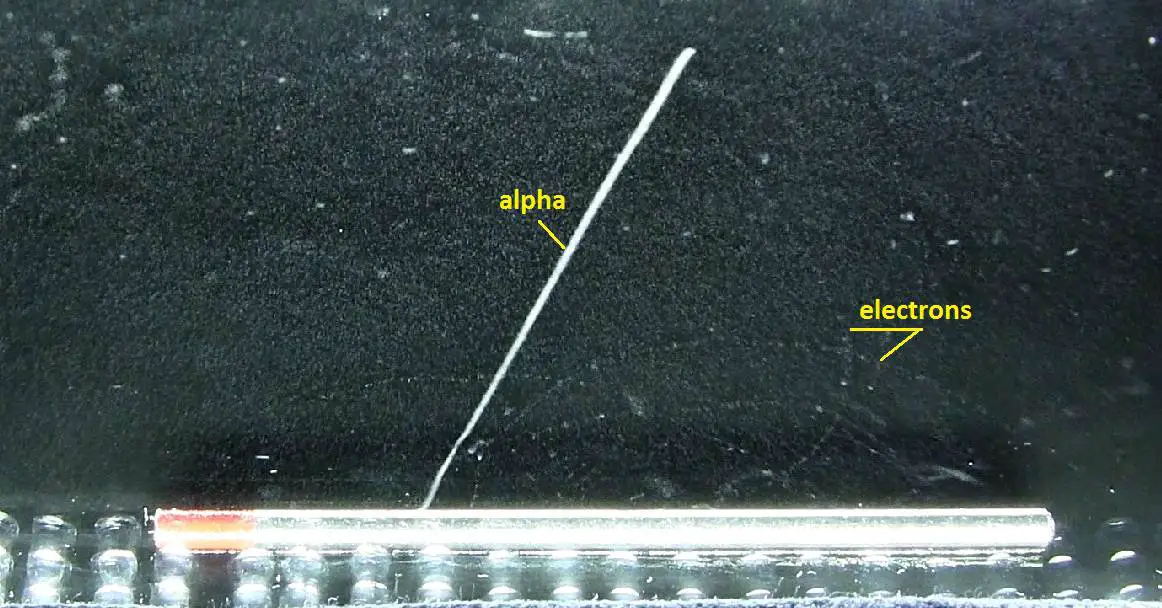
Alpha particles and electrons (deflected by a magnetic field) from a thorium rod in a cloud chamber. Source: wikipedia.org
Bubble chambers are particle detectors, that are based on similar principle as cloud chambers. In the bubble chamber, the tracks of subatomic particles are revealed as trails of bubbles in a liquid heated to just below its boiling point, usually liquid hydrogen. Bubble chambers can be made physically larger than cloud chambers, and since they are filled with much-denser liquid material, they reveal the tracks of much more energetic particles. An energetic charged particle (for example, an alpha or beta particle) interacts with the liquid and the liquid enters into a superheated, metastable phase. Around the ionization track the liquid vaporizes, forming microscopic bubbles. Bubble density around a track is proportional to a particle’s energy loss.
It must be emphasized that bubbles that in these devices form tracks grow on ions created by the passage of ionising particles. Thus, this ionisation process must be analysed. Each type of particle interacts in a different way, therefore knowledge of this interaction, how different particles deposit energy in the matter and how much energy particles deposit, is fundamental for our understanding of the problem. For example charged particles with high energies can directly ionize atoms. Alpha particles are fairly massive and carry a double positive charge, so they tend to travel only a short distance and do not penetrate very far into tissue if at all. However alpha particles will deposit their energy over a smaller volume (possibly only a few cells if they enter a body) and cause more damage to those few cells. As a result, alpha particle leave short but significant trace in the chamber.
Beta particles (electrons) are much smaller than alpha particles. They carry a single negative charge. They are more penetrating than alpha particles. They can travel several meters but deposit less energy at any one point along their paths than alpha particles. Therefore, beta particles leave longer but less visible trace in the chamber.
If a magnetic field is applied across the cloud chamber, positively and negatively charged particles will curve in opposite directions, according to the Lorentz force law.
Ionization and Track Information
It must be emphasized that drops that in these devices form tracks grow on ions created by the passage of ionising particles. Thus, this ionisation process must be analysed. Each type of particle interacts in a different way, therefore knowledge of this interaction, how different particles deposit energy in the matter and how much energy particles deposit, is fundamental for our understanding of the problem. For example charged particles with high energies can directly ionize atoms. Alpha particles are fairly massive and carry a double positive charge, so they tend to travel only a short distance and do not penetrate very far into tissue if at all. However alpha particles will deposit their energy over a smaller volume (possibly only a few cells if they enter a body) and cause more damage to those few cells. As a result, alpha particle leave short but significant trace in the chamber.
Beta particles (electrons) are much smaller than alpha particles. They carry a single negative charge. They are more penetrating than alpha particles. They can travel several meters but deposit less energy at any one point along their paths than alpha particles. Therefore, beta particles leave longer but less visible trace in the chamber.
If a magnetic field is applied across the cloud chamber, positively and negatively charged particles will curve in opposite directions, according to the Lorentz force law.
According to experimental data the specific ionisation dN/dx in cloud chambers, defined as the mean number of ions produced per unit of length by a passing particle, is well described to a first approximation both for electrons and for more massive particles by the Bethe equation.
Stopping Power – Bethe Formula
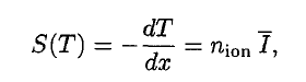
A convenient variable that describes the ionization properties of surrounding medium is the stopping power. The linear stopping power of material is defined as the ratio of the differential energy loss for the particle within the material to the corresponding differential path length:
,where T is the kinetic energy of the charged particle, nion is the number of electron-ion pairs formed per unit path length, and I denotes the average energy needed to ionize an atom in the medium. For charged particles, S increases as the particle velocity decreases. The classical expression that describes the specific energy loss is known as the Bethe formula. The non-relativistic formula was found by Hans Bethe in 1930. The relativistic version (see below) was found also by Hans Bethe in 1932.
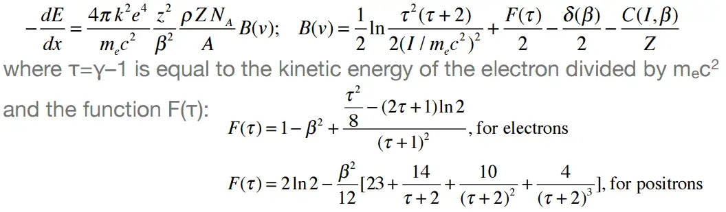
In this expression, m is the rest mass of the electron, β equals to v/c, what expresses the particle’s velocity relative to the speed of light, γ is the Lorentz factor of the particle, Q equals to its charge, Z is the atomic number of the medium and n is the atoms density in the volume. For nonrelativistic particles (heavy charged particles are mostly nonrelativistic), dT/dx is dependent on 1/v2. This is can be explained by the greater time the charged particle spends in the negative field of the electron, when the velocity is low.
Nature of an interaction of a beta radiation with matter is different from the alpha radiation, despite the fact that beta particles are also charged particles. In comparison with alpha particles, beta particles have much lower mass and they reach mostly relativistic energies. Their mass is equal to the mass of the orbital electrons with which they are interacting and unlike the alpha particle a much larger fraction of its kinetic energy can be lost in a single interaction. Since the beta particles mostly reach relativistic energies, the nonrelativistic Bethe formula cannot be used. For high energy electrons an similar expression has also been derived by Bethe to describe the specific energy loss due to excitation and ionization (the “collisional losses”).
Modified Bethe formula for beta particles.
Moreover, beta particles can interact via electron-nuclear interaction (elastic scattering off nuclei), which can significantly change the direction of beta particle. Therefore their path is not so straightforward. The beta particles follow a very zig-zag path through absorbing material, this resulting path of particle is longer than the linear penetration (range) into the material.
Beta particles also differ from other heavy charged particles in the fraction of energy lost by radiative process known as the bremsstrahlung. From classical theory, when a charged particle is accelerated or decelerated, it must radiate energy and the deceleration radiation is known as the bremsstrahlung (“braking radiation”).
Robert Reed Burn, Introduction to Nuclear Reactor Operation, 1988.
U.S. Department of Energy, Nuclear Physics and Reactor Theory. DOE Fundamentals Handbook, Volume 1 and 2. January 1993.
Paul Reuss, Neutron Physics. EDP Sciences, 2008. ISBN: 978-2759800414.
See also:
Cloud Chamber
We hope, this article, Bubble Chamber, helps you. If so, give us a like in the sidebar. Main purpose of this website is to help the public to learn some interesting and important information about radiation and dosimeters.
Positron paths in a cloud chamber trace the same helical path as an electron but rotate in the opposite direction with respect to the magnetic field direction due to their having the same magnitude of charge-to-mass ratio. Cloud Chamber and Discovery of Positron
Cloud chambers, also known as Wilson cloud chambers, are particle detectors, that were essential devices in early nuclear and particle physics research. Cloud chambers, one of the most simple instruments to study elementary particles, have been substituted by more modern detectors in actual research, but they still remain very interesting pedagogical apparatus.
Cloud Chamber and Discovery of Positron
Positrons are positively charged (+1e), almost massless particles. Their rest mass equal to 9.109 × 10⁻³¹ kg (510.998 keV/c2) (approximately 1/1836 that of the proton).
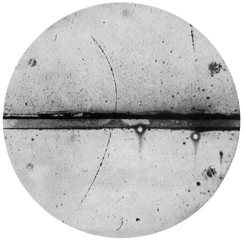
Antielectrons were discovered by Paul Dirac and Carl D. Anderson in 1932 and named positrons. They studied cosmic-ray collisions via a cloud chamber – a particle detector in which moving electrons (or positrons) leave behind trails as they move through the gas. Source: wikipedia.org License: Public Domain
Like all elementary particles, electrons exhibit properties of both particles and waves: they can collide with other particles and can be diffracted like light. The original idea for antiparticles came from a relativistic wave equation developed in 1928 by the English scientist P. A. M. Dirac (1902-1984). He realised that his relativistic version of the Schrödinger wave equation for electrons predicted the possibility of antielectrons. These were discovered by Paul Dirac and Carl D. Anderson in 1932 and named positrons. They studied cosmic-ray collisions via a cloud chamber – a particle detector in which moving electrons (or positrons) leave behind trails as they move through the gas. Positron paths in a cloud chamber trace the same helical path as an electron but rotate in the opposite direction with respect to the magnetic field direction due to their having the same magnitude of charge-to-mass ratio but with opposite charge and, therefore, opposite signed charge-to-mass ratios. Although Dirac did not himself use the term antimatter, its use follows on naturally enough from antielectrons, antiprotons, etc.
Robert Reed Burn, Introduction to Nuclear Reactor Operation, 1988.
U.S. Department of Energy, Nuclear Physics and Reactor Theory. DOE Fundamentals Handbook, Volume 1 and 2. January 1993.
Paul Reuss, Neutron Physics. EDP Sciences, 2008. ISBN: 978-2759800414.
See also:
Cloud Chamber
We hope, this article, Cloud Chamber and Discovery of Positron, helps you. If so, give us a like in the sidebar. Main purpose of this website is to help the public to learn some interesting and important information about radiation and dosimeters.
A diffusion cloud chamber differs from the expansion cloud chamber in that it is continuously sensitized to radiation, and in that the bottom must be cooled to a rather low temperature, generally colder than −26 °C (−15 °F). Radiation Dosimetry
Alpha particles and electrons (deflected by a magnetic field) from a thorium rod in a cloud chamber. Source: wikipedia.org
Cloud chambers, also known as Wilson cloud chambers, are particle detectors, that were essential devices in early nuclear and particle physics research. Cloud chambers, one of the most simple instruments to study elementary particles, have been substituted by more modern detectors in actual research, but they still remain very interesting pedagogical apparatus.
Expansion Cloud Chamber
In Wilson’s original chamber the air inside the sealed device was saturated with water vapor, then a diaphragm was used to expand the air inside the chamber (adiabatic expansion), cooling the air and starting to condense water vapor. Hence the name expansion cloud chamber is used. The first antiparticle, the positron, the muon, and the first strange particle, the kaon, were also first identified using cloud chamber.
Diffusion Cloud Chamber
Although diffusion cloud chambers were never broadly used in nuclear and particle physics research, being easy to build an carry they still remain interesting educational instruments. A diffusion cloud chamber differs from the expansion cloud chamber in that it is continuously sensitized to radiation, and in that the bottom must be cooled to a rather low temperature, generally colder than −26 °C (−15 °F). Instead of water vapor, alcohol is used because of its lower freezing point. Nowadays, they are an easy way of learning about and visualising elementary particles and radiation.
Robert Reed Burn, Introduction to Nuclear Reactor Operation, 1988.
U.S. Department of Energy, Nuclear Physics and Reactor Theory. DOE Fundamentals Handbook, Volume 1 and 2. January 1993.
Paul Reuss, Neutron Physics. EDP Sciences, 2008. ISBN: 978-2759800414.
See also:
Cloud Chamber
We hope, this article, Diffusion Cloud Chamber and Expansion Cloud Chamber, helps you. If so, give us a like in the sidebar. Main purpose of this website is to help the public to learn some interesting and important information about radiation and dosimeters.
The fundamental principle behind cloud chambers is the supersaturation of a vapor substance. Cloud Chamber – Principle of Operation
Alpha particles and electrons (deflected by a magnetic field) from a thorium rod in a cloud chamber. Source: wikipedia.org
Cloud chambers, also known as Wilson cloud chambers, are particle detectors, that were essential devices in early nuclear and particle physics research. Cloud chambers, one of the most simple instruments to study elementary particles, have been substituted by more modern detectors in actual research, but they still remain very interesting pedagogical apparatus.
Cloud Chamber – Principle of Operation
The fundamental principle behind them is the supersaturation of a vapor substance, a state in which the air, or any other gas, contains more vapour of that substance than it can hold in a stable equilibrium. An energetic charged particle (for example, an alpha or beta particle) interacts with the vapor mixture and creates a track of ions, which under supersaturation conditions act as condensation nuclei around which a mist-like trail of small droplets form if the gas mixture is at the point of condensation.
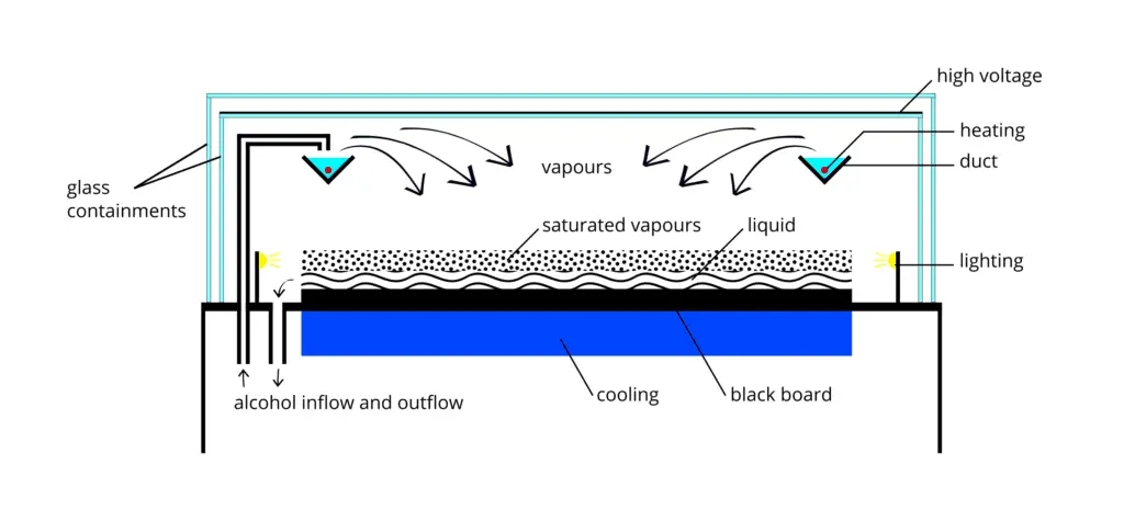
A diffusion-type cloud chamber. Alcohol (typically isopropanol) is evaporated by a heater in a duct in the upper part of the chamber. Cooling vapor descends to the black refrigerated plate, where it condenses. Due to the temperature gradient a layer of supersaturated vapor is formed above the bottom plate. In this region, radiation particles induce condensation and create cloud tracks. Source: wikipedia.org License: CC BY-SA 4.0
These droplets are visible as a “cloud” track that persist for several seconds while the droplets fall through the vapor. The condensation of the vapour on these nuclei allows visual identification of the trajectories of the particles, leading to a straightforward study of their properties. In Wilson’s original chamber the air inside the sealed device was saturated with water vapor, then a diaphragm was used to expand the air inside the chamber (adiabatic expansion), cooling the air and starting to condense water vapor. Hence the name expansion cloud chamber is used. The first antiparticle, the positron, the muon, and the first strange particle, the kaon, were also first identified using cloud chamber.
Robert Reed Burn, Introduction to Nuclear Reactor Operation, 1988.
U.S. Department of Energy, Nuclear Physics and Reactor Theory. DOE Fundamentals Handbook, Volume 1 and 2. January 1993.
Paul Reuss, Neutron Physics. EDP Sciences, 2008. ISBN: 978-2759800414.
See also:
Cloud Chamber
We hope, this article, Cloud Chamber – Principle of Operation, helps you. If so, give us a like in the sidebar. Main purpose of this website is to help the public to learn some interesting and important information about radiation and dosimeters.
We hope, this article, Particle Detection – Particle Detectors, helps you. If so, give us a like in the sidebar. Main purpose of this website is to help the public to learn some interesting and important information about radiation and dosimeters.
Cloud chambers, also known as Wilson cloud chambers, are particle detectors, that were essential devices in early nuclear and particle physics research. Radiation Dosimetry
Alpha particles and electrons (deflected by a magnetic field) from a thorium rod in a cloud chamber. Source: wikipedia.org
Cloud chambers, also known as Wilson cloud chambers, are particle detectors, that were essential devices in early nuclear and particle physics research. Cloud chambers, one of the most simple instruments to study elementary particles, have been substituted by more modern detectors in actual research, but they still remain very interesting pedagogical apparatus.
Cloud Chamber – Principle of Operation
The fundamental principle behind them is the supersaturation of a vapor substance, a state in which the air, or any other gas, contains more vapour of that substance than it can hold in a stable equilibrium. An energetic charged particle (for example, an alpha or beta particle) interacts with the vapor mixture and creates a track of ions, which under supersaturation conditions act as condensation nuclei around which a mist-like trail of small droplets form if the gas mixture is at the point of condensation.
A diffusion-type cloud chamber. Alcohol (typically isopropanol) is evaporated by a heater in a duct in the upper part of the chamber. Cooling vapor descends to the black refrigerated plate, where it condenses. Due to the temperature gradient a layer of supersaturated vapor is formed above the bottom plate. In this region, radiation particles induce condensation and create cloud tracks. Source: wikipedia.org License: CC BY-SA 4.0
These droplets are visible as a “cloud” track that persist for several seconds while the droplets fall through the vapor. The condensation of the vapour on these nuclei allows visual identification of the trajectories of the particles, leading to a straightforward study of their properties. In Wilson’s original chamber the air inside the sealed device was saturated with water vapor, then a diaphragm was used to expand the air inside the chamber (adiabatic expansion), cooling the air and starting to condense water vapor. Hence the name expansion cloud chamber is used. The first antiparticle, the positron, the muon, and the first strange particle, the kaon, were also first identified using cloud chamber.
Diffusion Cloud Chamber
Although diffusion cloud chambers were never broadly used in nuclear and particle physics research, being easy to build an carry they still remain interesting educational instruments. A diffusion cloud chamber differs from the expansion cloud chamber in that it is continuously sensitized to radiation, and in that the bottom must be cooled to a rather low temperature, generally colder than −26 °C (−15 °F). Instead of water vapor, alcohol is used because of its lower freezing point. Nowadays, they are an easy way of learning about and visualising elementary particles and radiation.
Ionization and Track Information
It must be emphasized that drops that in these devices form tracks grow on ions created by the passage of ionising particles. Thus, this ionisation process must be analysed. Each type of particle interacts in a different way, therefore knowledge of this interaction, how different particles deposit energy in the matter and how much energy particles deposit, is fundamental for our understanding of the problem. For example charged particles with high energies can directly ionize atoms. Alpha particles are fairly massive and carry a double positive charge, so they tend to travel only a short distance and do not penetrate very far into tissue if at all. However alpha particles will deposit their energy over a smaller volume (possibly only a few cells if they enter a body) and cause more damage to those few cells. As a result, alpha particle leave short but significant trace in the chamber.
Beta particles (electrons) are much smaller than alpha particles. They carry a single negative charge. They are more penetrating than alpha particles. They can travel several meters but deposit less energy at any one point along their paths than alpha particles. Therefore, beta particles leave longer but less visible trace in the chamber.
If a magnetic field is applied across the cloud chamber, positively and negatively charged particles will curve in opposite directions, according to the Lorentz force law.
According to experimental data the specific ionisation dN/dx in cloud chambers, defined as the mean number of ions produced per unit of length by a passing particle, is well described to a first approximation both for electrons and for more massive particles by the Bethe equation.
Stopping Power – Bethe Formula
A convenient variable that describes the ionization properties of surrounding medium is the stopping power. The linear stopping power of material is defined as the ratio of the differential energy loss for the particle within the material to the corresponding differential path length:
,where T is the kinetic energy of the charged particle, nion is the number of electron-ion pairs formed per unit path length, and I denotes the average energy needed to ionize an atom in the medium. For charged particles, S increases as the particle velocity decreases. The classical expression that describes the specific energy loss is known as the Bethe formula. The non-relativistic formula was found by Hans Bethe in 1930. The relativistic version (see below) was found also by Hans Bethe in 1932.
In this expression, m is the rest mass of the electron, β equals to v/c, what expresses the particle’s velocity relative to the speed of light, γ is the Lorentz factor of the particle, Q equals to its charge, Z is the atomic number of the medium and n is the atoms density in the volume. For nonrelativistic particles (heavy charged particles are mostly nonrelativistic), dT/dx is dependent on 1/v2. This is can be explained by the greater time the charged particle spends in the negative field of the electron, when the velocity is low.
Nature of an interaction of a beta radiation with matter is different from the alpha radiation, despite the fact that beta particles are also charged particles. In comparison with alpha particles, beta particles have much lower mass and they reach mostly relativistic energies. Their mass is equal to the mass of the orbital electrons with which they are interacting and unlike the alpha particle a much larger fraction of its kinetic energy can be lost in a single interaction. Since the beta particles mostly reach relativistic energies, the nonrelativistic Bethe formula cannot be used. For high energy electrons an similar expression has also been derived by Bethe to describe the specific energy loss due to excitation and ionization (the “collisional losses”).
Modified Bethe formula for beta particles.
Moreover, beta particles can interact via electron-nuclear interaction (elastic scattering off nuclei), which can significantly change the direction of beta particle. Therefore their path is not so straightforward. The beta particles follow a very zig-zag path through absorbing material, this resulting path of particle is longer than the linear penetration (range) into the material.
Beta particles also differ from other heavy charged particles in the fraction of energy lost by radiative process known as the bremsstrahlung. From classical theory, when a charged particle is accelerated or decelerated, it must radiate energy and the deceleration radiation is known as the bremsstrahlung (“braking radiation”).
Cloud Chamber and Discovery of Positron
Positrons are positively charged (+1e), almost massless particles. Their rest mass equal to 9.109 × 10⁻³¹ kg (510.998 keV/c2) (approximately 1/1836 that of the proton).
Antielectrons were discovered by Paul Dirac and Carl D. Anderson in 1932 and named positrons. They studied cosmic-ray collisions via a cloud chamber – a particle detector in which moving electrons (or positrons) leave behind trails as they move through the gas. Source: wikipedia.org License: Public Domain
Like all elementary particles, electrons exhibit properties of both particles and waves: they can collide with other particles and can be diffracted like light. The original idea for antiparticles came from a relativistic wave equation developed in 1928 by the English scientist P. A. M. Dirac (1902-1984). He realised that his relativistic version of the Schrödinger wave equation for electrons predicted the possibility of antielectrons. These were discovered by Paul Dirac and Carl D. Anderson in 1932 and named positrons. They studied cosmic-ray collisions via a cloud chamber – a particle detector in which moving electrons (or positrons) leave behind trails as they move through the gas. Positron paths in a cloud chamber trace the same helical path as an electron but rotate in the opposite direction with respect to the magnetic field direction due to their having the same magnitude of charge-to-mass ratio but with opposite charge and, therefore, opposite signed charge-to-mass ratios. Although Dirac did not himself use the term antimatter, its use follows on naturally enough from antielectrons, antiprotons, etc.
Bubble Chamber
Bubble chambers are particle detectors, that are based on similar principle as cloud chambers. In the bubble chamber, the tracks of subatomic particles are revealed as trails of bubbles in a liquid heated to just below its boiling point, usually liquid hydrogen. Bubble chambers can be made physically larger than cloud chambers, and since they are filled with much-denser liquid material, they reveal the tracks of much more energetic particles. An energetic charged particle (for example, an alpha or beta particle) interacts with the liquid and the liquid enters into a superheated, metastable phase. Around the ionization track the liquid vaporizes, forming microscopic bubbles. Bubble density around a track is proportional to a particle’s energy loss.
It must be emphasized that bubbles that in these devices form tracks grow on ions created by the passage of ionising particles. Thus, this ionisation process must be analysed. Each type of particle interacts in a different way, therefore knowledge of this interaction, how different particles deposit energy in the matter and how much energy particles deposit, is fundamental for our understanding of the problem. For example charged particles with high energies can directly ionize atoms. Alpha particles are fairly massive and carry a double positive charge, so they tend to travel only a short distance and do not penetrate very far into tissue if at all. However alpha particles will deposit their energy over a smaller volume (possibly only a few cells if they enter a body) and cause more damage to those few cells. As a result, alpha particle leave short but significant trace in the chamber.
Beta particles (electrons) are much smaller than alpha particles. They carry a single negative charge. They are more penetrating than alpha particles. They can travel several meters but deposit less energy at any one point along their paths than alpha particles. Therefore, beta particles leave longer but less visible trace in the chamber.
If a magnetic field is applied across the cloud chamber, positively and negatively charged particles will curve in opposite directions, according to the Lorentz force law.
Robert Reed Burn, Introduction to Nuclear Reactor Operation, 1988.
U.S. Department of Energy, Nuclear Physics and Reactor Theory. DOE Fundamentals Handbook, Volume 1 and 2. January 1993.
Paul Reuss, Neutron Physics. EDP Sciences, 2008. ISBN: 978-2759800414.
See also:
Radiation Detection
We hope, this article, Cloud Chamber, helps you. If so, give us a like in the sidebar. Main purpose of this website is to help the public to learn some interesting and important information about radiation and dosimeters.
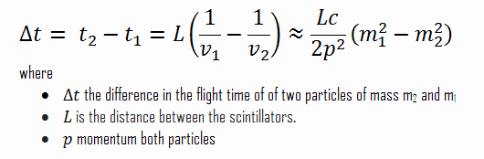
Time of flight detectors (TOF) determine charged particle velocity by measuring the time required to travel from the interaction point to the time of flight detector, or between two detectors. As was written, scintillation counters (especially with organic scintillators) can provide excellent time resolution and therefore they can be used as a time of flight detector to discriminate between a lighter and a heavier elementary particle of same momentum using their time of flight. The first of the scintillators activates a clock upon being hit while the other stops the clock upon being hit. If the two masses are denoted by m1 and m2 and have velocities v1 and v2 then the time of flight difference is given by:
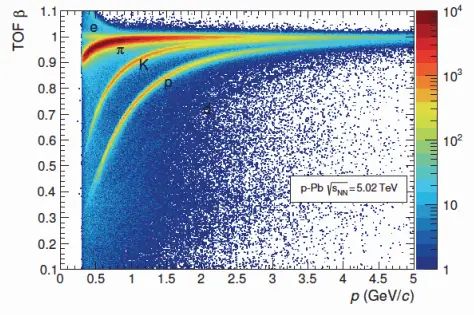
These detectors can be also used to measure time of flight for reaching some scintillation counter located at a distance L from the point of origin of the particle to determine the velocity and therefore the rest mass of the particle, thus they can be used for particle separation.
Distribution of β as measured by the TOF detector as a function of momentum for particles reaching TOF in p–Pb interactions. ALICE experiment LHC Cern. Source: Particle Detectors; Raffaella De Vita; INFN – Sezione di Genova
Robert Reed Burn, Introduction to Nuclear Reactor Operation, 1988.
U.S. Department of Energy, Nuclear Physics and Reactor Theory. DOE Fundamentals Handbook, Volume 1 and 2. January 1993.
Paul Reuss, Neutron Physics. EDP Sciences, 2008. ISBN: 978-2759800414.
See also:
Radiation Detection
We hope, this article, Time of Flight – TOF Detector, helps you. If so, give us a like in the sidebar. Main purpose of this website is to help the public to learn some interesting and important information about radiation and dosimeters.
In particle physics, a calorimeter is an experimental device that measures the energy a particle loses as it passes through. Electromagnetic calorimeters and hadronic calorimeters. Radiation Dosimetry
In particle physics , a calorimeter is an experimental device that measures the energy a particle loses as it passes through. Calorimeters are blocks of instrumented material in which particles to be measured are fully absorbed and their energy transformed into a measurable quantity. A signal detected by a calorimeter is proportional to that deposited energy. Most particles enter the calorimeter and initiate a particle shower and the particles’ energy is deposited in the calorimeter, collected, and measured. The interaction of the incident particle with the detector can be via electromagnetic interaction or via strong processes. Therefore, calorimeters can be broadly divided into:
Electromagnetic calorimeters are used to measure the energy of electrons and photons as they interact (e.g. bremsstrahlung, pair production) with the electrically charged particles in matter. An electromagnetic shower begins when a high-energy electron, positron or photon enters a material. At high energies (above a few MeV, below which photoelectric effect and Compton scattering are dominant), photons interact with matter primarily via pair production — that is, they convert into an electron-positron pair, interacting with an atomic nucleus or electron in order to conserve momentum.
Hadronic calorimeters are used to measure mainly hadrons through their strong and electromagnetic interactions. Similarly as for electromagnetic showers, hadrons can deposit energy in matter through a series of successive interactions. The physical process that cause the propagation of a hadron shower are considerably different from the processes in electromagnetic showers. Hadrons are relatively massive, and cannot radiate much of their energy through bremsstrahlung, they lose their energy mainly through multiple nuclear collisions.
Large calorimeters were developed during the early 1960s, especially for application in experiments dealing with highenergy cosmic rays, and they have become exceedingly important tools for measuring energies of particles produced at large accelerators.
Robert Reed Burn, Introduction to Nuclear Reactor Operation, 1988.
U.S. Department of Energy, Nuclear Physics and Reactor Theory. DOE Fundamentals Handbook, Volume 1 and 2. January 1993.
Paul Reuss, Neutron Physics. EDP Sciences, 2008. ISBN: 978-2759800414.
See also:
Radiation Detection
We hope, this article, Calorimeter, helps you. If so, give us a like in the sidebar. Main purpose of this website is to help the public to learn some interesting and important information about radiation and dosimeters.
Cherenkov Detector vs Scintillation Detector. Typical scintillator detectors have a decay time measured in microseconds while Cherenkov radiation is nearly instantaneous. Radiation Dosimetry
Cherenkov Detectors
A Cherenkov detector is a particle detector, which is based on detection of Cherenkov radiation (visible light or UV photons). In contrast to a scintillation counter the light production is instantaneous. Typical scintillator detectors have a decay time measured in microseconds while Cherenkov radiation is nearly instantaneous and with fast pulse processing equipment can be measured in picoseconds. Cherenkov counters are used mainly for the particle identification, i.e. for the determination of particle masses. Cherenkov counters contain two main elements:
a radiator through which the charged particle passes,
The Cherenkov radiation, which is produced in the radiator, is electromagnetic radiation emitted when a charged particle (such as an electron) moves through a dielectric medium faster than the phase velocity of light in that medium. Particles exceeding the phase velocity of light result in polarization along the axis of motion creating a dipole field. When this field collapses, an electromagnetic pulse (Cherenkov radiation) is emitted in the forward direction.
Cherenkov radiation is commonly produced in dielectric materials through Compton electrons or pair-production electrons and positrons. The intensity of light produced by this process is much less than that of luminescence (the basis for scintillation detector operation) requiring more sensitive optical photon detection equipment such as low light photo-multiplier tubes (PMT). Cherenkov counters may be classified as either imaging or threshold types, depending on whether they do or do not make use of Cherenkov angle (θ) information. In the simple case of a threshold detector the mass-dependent threshold energy allows the discrimination between a lighter particle (which does radiate) and a heavier particle (which does not radiate) of the same energy or momentum. Imaging counters may be used to track particles as well as identify them. Although devices using Cherenkov radiation are often thought of as particle identification (PID) detectors, in practice, they are widely used over a much broader range of applications; including:
A scintillation counter or scintillation detector is a radiation detector which uses the effect known as scintillation. Scintillation is a flash of light produced in a transparent material by the passage of a particle (an electron, an alpha particle, an ion, or a high-energy photon). Scintillation occurs in the scintillator, which is a key part of a scintillation detector. In general, a scintillation detector consists of:
Scintillator. A scintillator generates photons in response to incident radiation.
Photodetector. A sensitive photodetector (usually a photomultiplier tube (PMT), a charge-coupled device (CCD) camera, or a photodiode), which converts the light to an electrical signal and electronics to process this signal.
The basic principle of operation involves the radiation reacting with a scintillator, which produces a series of flashes of varying intensity. The intensity of the flashes is proportional to the energy of the radiation. This feature is very important. These counters are suited to measure the energy of gamma radiation (gamma spectroscopy) and, therefore, can be used to identify gamma emitting isotopes.
Robert Reed Burn, Introduction to Nuclear Reactor Operation, 1988.
U.S. Department of Energy, Nuclear Physics and Reactor Theory. DOE Fundamentals Handbook, Volume 1 and 2. January 1993.
Paul Reuss, Neutron Physics. EDP Sciences, 2008. ISBN: 978-2759800414.
See also:
Cherenkov Detectors
We hope, this article, Cherenkov Detector vs Scintillation Detector, helps you. If so, give us a like in the sidebar. Main purpose of this website is to help the public to learn some interesting and important information about radiation and dosimeters.