Advantages and Disadvantages of Geiger-Mueller Counter. G-M counters are mainly used for portable instrumentation due to its sensitivity, simple counting circuit, and ability to detect low-level radiation. Radiation Dosimetry
Detector of Ionizing Radiation – Geiger Tube
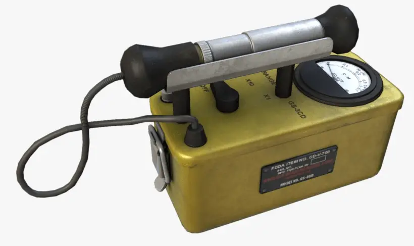
The Geiger counter, also known as the Geiger-Mueller counter, is electrical device that detects various types of ionizing radiation. This device is named after the two physicists who invented the counter in 1928. Mueller was a student of Hans Geiger. Geiger counter is widely used in applications such as radiation dosimetry, radiological protection, experimental physics, and the nuclear industry. A Geiger counter consists of a Geiger-Müller tube (the sensing element which detects the radiation) and the processing electronics, which displays the result.
Geiger counter can detect ionizing radiation such as alpha and beta particles, neutrons, and gamma rays using the ionization effect produced in a Geiger–Müller tube, which gives its name to the instrument. The voltage of detector is adjusted so that the conditions correspond to the Geiger-Mueller region.
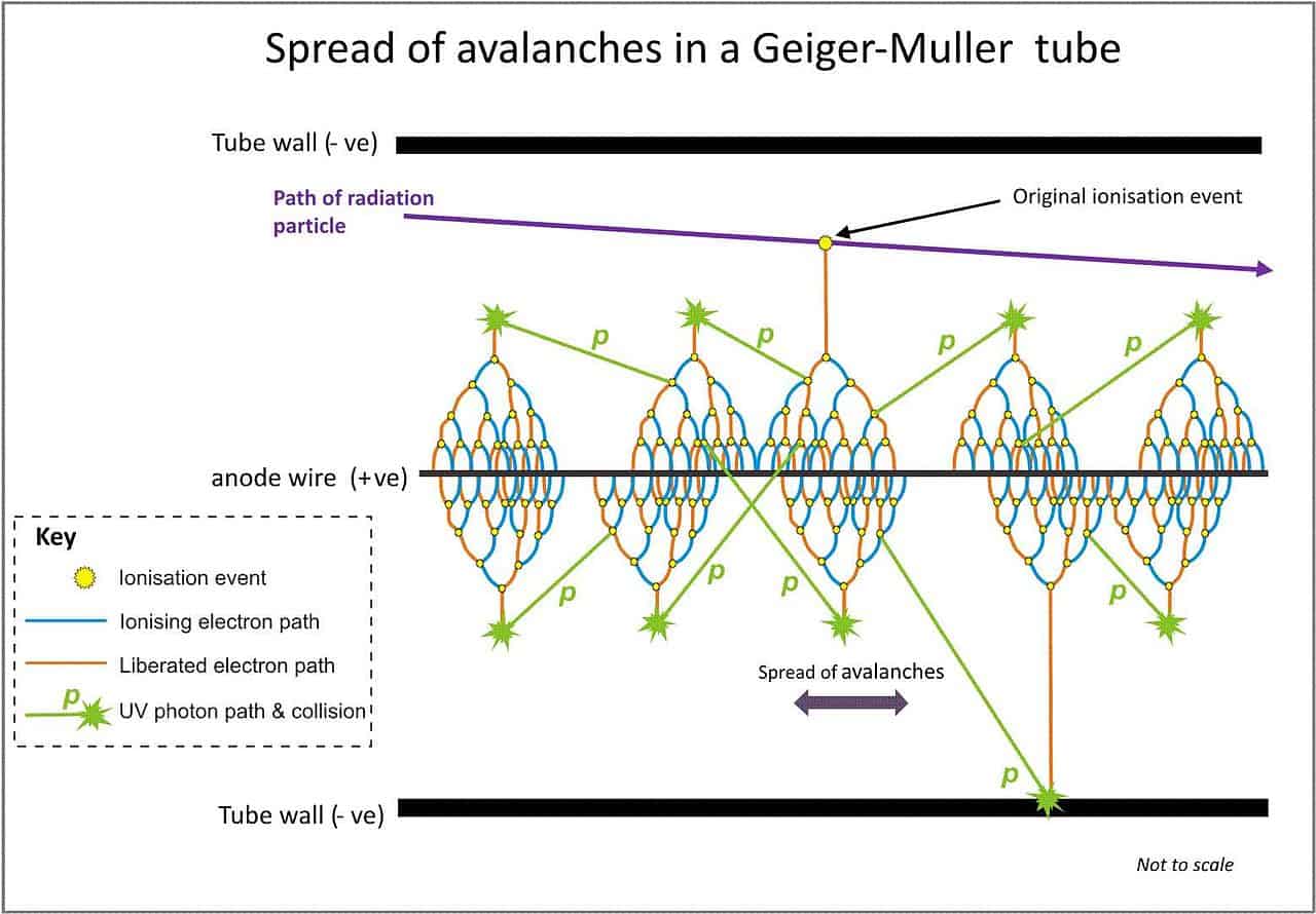
Visualisation of the spread of Townsend avalanches by means of UV photons. Source: wikpedia.org License: CC BY-SA 3.0
Advantages of Geiger-Mueller Counter
High Amplification. A strong signal (the amplification factor can reach about 1010) is produced by these avalanches with shape and height independently of the primary ionization and the energy of the detected photon. The voltage pulse in this case would be a large and easily detectable ≈ 1.6 V. The technical advantage of a Geiger counter is its simplicity of construction and its insensitivity to small voltage fluctuations. Since the process of charge amplification greatly improves the signal-to-noise ratio of the detector, the subsequent electronic amplification is usually not required.
Simplicity. G-M counters are mainly used for portable instrumentation due to its sensitivity, simple counting circuit, and ability to detect low-level radiation. G-M detectors are generally more sensitive to low energy and low intensity radiations than are proportional or ion chamber detectors.
Simpler Electronics. G-M detectors can be used with simpler electronics packages. The input
sensitivity of a typical G-M survey instrument is 300-800 millivolt, while the input
sensitivity of a typical proportional survey instrument is 2 millivolt.
Disadvantages of Geiger-Mueller Counter
No particle identification, no energy resolution. Since the pulse height is independent of the type and energy of radiation, discrimination is not possible. There is no information whatsoever on the nature of the ionization that caused the pulse. G-M detectors can not discriminate against different types of radiation (α, β, γ), nor against various radiation energies. This is because the size of the avalanche is independent of the primary ionization which created it.
Dead Time. Because of the large avalanche induced by any ionization, a Geiger counter takes a long time (about 1 ms) to recover between successive pulses. Therefore, Geiger counters are not able to measure high radiation rates due to the “dead time” of the tube.
Robert Reed Burn, Introduction to Nuclear Reactor Operation, 1988.
U.S. Department of Energy, Nuclear Physics and Reactor Theory. DOE Fundamentals Handbook, Volume 1 and 2. January 1993.
Paul Reuss, Neutron Physics. EDP Sciences, 2008. ISBN: 978-2759800414.
See also:
Geiger Counter
We hope, this article, Advantage and Disadvantage of Geiger-Mueller Counters, helps you. If so, give us a like in the sidebar. Main purpose of this website is to help the public to learn some interesting and important information about radiation and dosimeters.
In general, the Geiger counter and also the proportional counter are types of gaseous ionization detectors. Proportional counters or Geiger counters are almost always used in pulse mode. Radiation Dosimetry
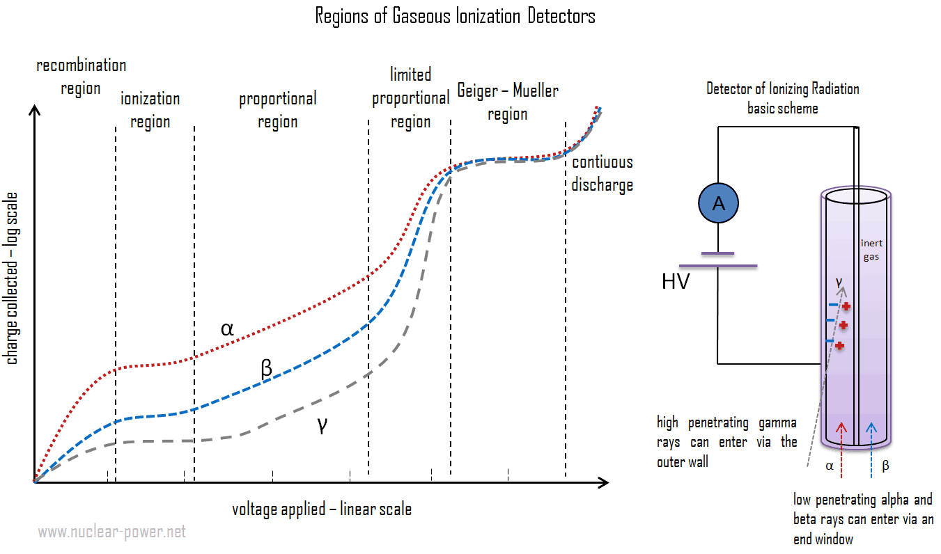
In general, the Geiger counter and also the proportional counter are types of gaseous ionization detectors. These can be categorized according to the voltage applied to the detector:
As with other detectors, ionization chambers can be operated in current or pulse mode. In contrast, proportional counters or Geiger counters are almost always used in pulse mode. Detectors of ionizing radiation can be used both for activity measurements as well as for dose measurement. With knowledge about the energy needed to form an pair of ions – the dose can be obtained.
Geiger Counter
The Geiger counter, also known as the Geiger-Mueller counter, is electrical device that detects various types of ionizing radiation. This device is named after the two physicists who invented the counter in 1928. Mueller was a student of Hans Geiger. Geiger counter is widely used in applications such as radiation dosimetry, radiological protection, experimental physics, and the nuclear industry. A Geiger counter consists of a Geiger-Müller tube (the sensing element which detects the radiation) and the processing electronics, which displays the result.
Geiger counter can detect ionizing radiation such as alpha and beta particles, neutrons, and gamma rays using the ionization effect produced in a Geiger–Müller tube, which gives its name to the instrument. The voltage of detector is adjusted so that the conditions correspond to the Geiger-Mueller region.
Advantages of Geiger-Mueller Counter
High Amplification. A strong signal (the amplification factor can reach about 1010) is produced by these avalanches with shape and height independently of the primary ionization and the energy of the detected photon. The voltage pulse in this case would be a large and easily detectable ≈ 1.6 V. The technical advantage of a Geiger counter is its simplicity of construction and its insensitivity to small voltage fluctuations. Since the process of charge amplification greatly improves the signal-to-noise ratio of the detector, the subsequent electronic amplification is usually not required.
Simplicity. G-M counters are mainly used for portable instrumentation due to its sensitivity, simple counting circuit, and ability to detect low-level radiation. G-M detectors are generally more sensitive to low energy and low intensity radiations than are proportional or ion chamber detectors.
Simpler Electronics. G-M detectors can be used with simpler electronics packages. The input
sensitivity of a typical G-M survey instrument is 300-800 millivolt, while the input
sensitivity of a typical proportional survey instrument is 2 millivolt.
Disadvantages of Geiger-Mueller Counter
No particle identification, no energy resolution. Since the pulse height is independent of the type and energy of radiation, discrimination is not possible. There is no information whatsoever on the nature of the ionization that caused the pulse. G-M detectors can not discriminate against different types of radiation (α, β, γ), nor against various radiation energies. This is because the size of the avalanche is independent of the primary ionization which created it.
Dead Time. Because of the large avalanche induced by any ionization, a Geiger counter takes a long time (about 1 ms) to recover between successive pulses. Therefore, Geiger counters are not able to measure high radiation rates due to the “dead time” of the tube.
Proportional Counter
A proportional counter, also known as the proportional detector, is an electrical device that detects various types of ionizing radiation. The voltage of detector is adjusted so that the conditions correspond to the proportional region. In this region, the voltage is high enough to provide the primary electrons with sufficient acceleration and energy so that they can ionize additional atoms of the medium. These secondary ions (gas amplification) formed are also accelerated causing an effect known as Townsend avalanches, which creates a single large electrical pulse.
Advantages of Proportional Counters
Amplification. Gaseous proportional counters usually operate in high electric fields of the order of 10 kV/cm and achieve typical amplification factors of about 105. Since the amplification factor is strongly dependent on the applied voltage, the charge collected (output signal) is also dependent on the applied voltage and proportional counters require constant voltage. The high amplification factor of the proportional counter is the major advantage over the ionization chamber.
Sensitivity. The process of charge amplification greatly improves the signal-to-noise ratio of the detector and reduces the subsequent electronic amplification required. Since the process of charge amplification greatly improves the signal-to-noise ratio of the detector, the subsequent electronic amplification is usually not required. Proportional counter detection instruments are very sensitive to low levels of radiation. Moreover, when measuring current output, a proportional detector is useful for dose rates
since the output signal is proportional to the energy deposited by ionization and therefore proportional to the dose rate.
Spectroscopy. By proper functional arrangements, modifications, and biasing, the proportional counter can be used to detect alpha, beta, gamma, or neutron radiation in mixed radiation fields. Moreover, proportional counters are capable of particle identification and energy measurement (spectroscopy). The pulse height reflects the energy deposited by the incident radiation in the detector gas. As such, it is possible to distinguish the larger pulses produced by alpha particles from the smaller pulses produced by beta particles or gamma rays.
Disadvantages of Proportional Counters
Constant Voltage. When instruments are operated in the proportional region, the voltage must be kept constant. If a voltage remains constant the gas amplification factor also does not change. The main drawback to using proportional counters in portable instruments is that they require a very stable power supply and amplifier to ensure constant operating conditions (in the middle of the proportional region). This is difficult to provide in a portable instrument, and that is why proportional counters tend to be used more in fixed or lab instruments.
Quenching. For each electron collected in the chamber, there is a positively charged gas ion left over. These gas ions are heavy compared to an electron and move much more slowly. Free electrons are much lighter than the positive ions, thus, they are drawn toward the positive central electrode much faster than the positive ions are drawn to the chamber wall. The resulting cloud of positive ions near the electrode leads to distortions in gas multiplication. In practice the termination of the avalanche is improved by the use of “quenching” techniques.
This diagram shows the number of ion pairs generated in the gas-filled detector, which varies according to the applied voltage for constant incident radiation. The voltages can vary widely depending upon the detector geometry and the gas type and pressure. This figure schematically indicates the different voltage regions for alpha, beta and gamma rays. There are six main practical operating regions, where three (ionization, proportional and Geiger-Mueller region) are useful to detect ionizing radiation. Alpha particles are more ionising than beta particles and than gamma rays, so more current is produced in the ion chamber region by alpha than beta and gamma, but the particles cannot be differentiated. More current is produced in the proportional counting region by alpha particles than beta, but by the nature of proportional counting it is possible to differentiate alpha, beta and gamma pulses. In the Geiger region, there is no differentiation of alpha and beta as any single ionisation event in the gas results in the same current output.
Robert Reed Burn, Introduction to Nuclear Reactor Operation, 1988.
U.S. Department of Energy, Nuclear Physics and Reactor Theory. DOE Fundamentals Handbook, Volume 1 and 2. January 1993.
Paul Reuss, Neutron Physics. EDP Sciences, 2008. ISBN: 978-2759800414.
See also:
Geiger Counter
We hope, this article, Geiger Counter vs Proportional Counter, helps you. If so, give us a like in the sidebar. Main purpose of this website is to help the public to learn some interesting and important information about radiation and dosimeters.
In general, the Geiger counter and also the ionization chamber are types of gaseous ionization detectors. Ionization chambers can be operated in current or pulse mode. In contrast, Geiger counters are almost always used in pulse mode. Radiation Dosimetry
In general, the Geiger counter and also the ionization chamber are types of gaseous ionization detectors. These can be categorized according to the voltage applied to the detector:
As with other detectors, ionization chambers can be operated in current or pulse mode. In contrast, proportional counters or Geiger counters are almost always used in pulse mode. Detectors of ionizing radiation can be used both for activity measurements as well as for dose measurement. With knowledge about the energy needed to form an pair of ions – the dose can be obtained.
Geiger Counter
The Geiger counter, also known as the Geiger-Mueller counter, is electrical device that detects various types of ionizing radiation. This device is named after the two physicists who invented the counter in 1928. Mueller was a student of Hans Geiger. Geiger counter is widely used in applications such as radiation dosimetry, radiological protection, experimental physics, and the nuclear industry. A Geiger counter consists of a Geiger-Müller tube (the sensing element which detects the radiation) and the processing electronics, which displays the result.
Geiger counter can detect ionizing radiation such as alpha and beta particles, neutrons, and gamma rays using the ionization effect produced in a Geiger–Müller tube, which gives its name to the instrument. The voltage of detector is adjusted so that the conditions correspond to the Geiger-Mueller region.
Advantages of Geiger-Mueller Counter
High Amplification. A strong signal (the amplification factor can reach about 1010) is produced by these avalanches with shape and height independently of the primary ionization and the energy of the detected photon. The voltage pulse in this case would be a large and easily detectable ≈ 1.6 V. The technical advantage of a Geiger counter is its simplicity of construction and its insensitivity to small voltage fluctuations. Since the process of charge amplification greatly improves the signal-to-noise ratio of the detector, the subsequent electronic amplification is usually not required.
Simplicity. G-M counters are mainly used for portable instrumentation due to its sensitivity, simple counting circuit, and ability to detect low-level radiation. G-M detectors are generally more sensitive to low energy and low intensity radiations than are proportional or ion chamber detectors.
Simpler Electronics. G-M detectors can be used with simpler electronics packages. The input
sensitivity of a typical G-M survey instrument is 300-800 millivolt, while the input
sensitivity of a typical proportional survey instrument is 2 millivolt.
Disadvantages of Geiger-Mueller Counter
No particle identification, no energy resolution. Since the pulse height is independent of the type and energy of radiation, discrimination is not possible. There is no information whatsoever on the nature of the ionization that caused the pulse. G-M detectors can not discriminate against different types of radiation (α, β, γ), nor against various radiation energies. This is because the size of the avalanche is independent of the primary ionization which created it.
Dead Time. Because of the large avalanche induced by any ionization, a Geiger counter takes a long time (about 1 ms) to recover between successive pulses. Therefore, Geiger counters are not able to measure high radiation rates due to the “dead time” of the tube.
Ionization Chamber
Theionization chamber, also known as the ion chamber, is electrical device that detects various types of ionizing radiation. The voltage of detector is adjusted so that the conditions correspond to the ionization region. The voltage is not high enough to produce gas amplification (secondary ionization).
Advantages of Ionization Chambers
Current mode. Ionization chambers are preferred for high radiation dose rates because they have no “dead time”, a phenomenon which affects the accuracy of the Geiger-Mueller tube at high dose rates. This is due to the fact, there is no inherent amplification of signal in the operating medium and therefore these types of counters do not require much time to recover from large currents. In addition, because there is no amplification, they provide excellent energy resolution, which is limited primarily by electronic noise. Ionization chambers can be operated in current or pulse mode. In contrast, proportional counters or Geiger counters are almost always used in pulse mode. Detectors of ionizing radiation can be used both for activity measurements as well as for dose measurement. With knowledge about the energy needed to form an pair of ions – the dose can be obtained. The flat plate design is preferred because it has a well-defined active volume and ensures that ions will not collect on the insulators and cause a distortion of the electric field.
Simplicity. Output current is independent of detector operating voltage. Observe the flat region of the curve in the ion chamber region. As a result, less regulated and thereby less expensive and more portable power supplies can be used with ion chamber instruments, and still offer a reasonably accurate response.
Neutron Detection. In nuclear reactors, ionization chambers in current mode are often used to detect neutrons and belong to the Nuclear Instrumentation System (NIS). For example, if the inner surface of the ionization chamber is coated with a thin coat of boron, the (n,alpha) reaction can take place. Most of (n,alpha) reactions of thermal neutrons are 10B(n,alpha)7Li reactions accompanied by 0.48 MeV gamma emission. Moreover, isotope boron-10 has high (n,alpha) reaction cross-section along the entire neutron energy spectrum. The alpha particle causes ionization within the chamber, and ejected electrons cause further secondary ionizations. Another method for detecting neutrons using an ionization chamber is to use the gas boron trifluoride (BF3) instead of air in the chamber. The incoming neutrons produce alpha particles when they react with the boron atoms in the detector gas. Either method may be used to detect neutrons in nuclear reactor.
Disadvantages of Ionization Chambers
No Charge Amplification. Detectors in the ionization region operate at a low electric field strength, selected such that no gas multiplication takes place. The charge collected (output signal) is independent of the applied voltage and for single minimum-ionizing particles tends to be quite small and usually require special low-noise amplifiers for attaining efficient operating performance. In air, the average energy needed to produce an ion is about 34 eV, therefore a 1 MeV radiation completely absorbed in the detector produces about 3 x 10⁴ pair of ions. However it is a small signal, this signal can be considerably amplified using standard electronics. A current of 1 micro-ampere consists of about 1012 electrons per second.
Low Density. Gamma rays deposit significantly lower amount of energy to the detector than other particles. The efficiency of the chamber can be further increased by the use of a high pressure gas.
For alpha and beta particles to be detected by ionization chambers, they must be provided with a thin window. This “end-window” must be thin enough for the alpha and beta particles to penetrate. However, a window of almost any thickness will prevent an alpha particle from entering the chamber. The window is usually made of mica with a density of about 1.5 – 2.0 mg/cm2.
This diagram shows the number of ion pairs generated in the gas-filled detector, which varies according to the applied voltage for constant incident radiation. The voltages can vary widely depending upon the detector geometry and the gas type and pressure. This figure schematically indicates the different voltage regions for alpha, beta and gamma rays. There are six main practical operating regions, where three (ionization, proportional and Geiger-Mueller region) are useful to detect ionizing radiation. Alpha particles are more ionising than beta particles and than gamma rays, so more current is produced in the ion chamber region by alpha than beta and gamma, but the particles cannot be differentiated. More current is produced in the proportional counting region by alpha particles than beta, but by the nature of proportional counting it is possible to differentiate alpha, beta and gamma pulses. In the Geiger region, there is no differentiation of alpha and beta as any single ionisation event in the gas results in the same current output.
Robert Reed Burn, Introduction to Nuclear Reactor Operation, 1988.
U.S. Department of Energy, Nuclear Physics and Reactor Theory. DOE Fundamentals Handbook, Volume 1 and 2. January 1993.
Paul Reuss, Neutron Physics. EDP Sciences, 2008. ISBN: 978-2759800414.
See also:
Geiger Counter
We hope, this article, Geiger Counter vs Ionization Chamber, helps you. If so, give us a like in the sidebar. Main purpose of this website is to help the public to learn some interesting and important information about radiation and dosimeters.
In general, the ionization chamber and also the proportional counter are types of gaseous ionization detectors. Ionization chambers can be operated in current or pulse mode. In contrast, proportional counters are almost always used in pulse mode. Radiation Dosimetry
In general, the ionization chamber and also the proportional counter are types of gaseous ionization detectors. These can be categorized according to the voltage applied to the detector:
As with other detectors, ionization chambers can be operated in current or pulse mode. In contrast, proportional counters or Geiger counters are almost always used in pulse mode. Detectors of ionizing radiation can be used both for activity measurements as well as for dose measurement. With knowledge about the energy needed to form an pair of ions – the dose can be obtained.
Ionization Chamber
Theionization chamber, also known as the ion chamber, is electrical device that detects various types of ionizing radiation. The voltage of detector is adjusted so that the conditions correspond to the ionization region. The voltage is not high enough to produce gas amplification (secondary ionization).
Advantages of Ionization Chambers
Current mode. Ionization chambers are preferred for high radiation dose rates because they have no “dead time”, a phenomenon which affects the accuracy of the Geiger-Mueller tube at high dose rates. This is due to the fact, there is no inherent amplification of signal in the operating medium and therefore these types of counters do not require much time to recover from large currents. In addition, because there is no amplification, they provide excellent energy resolution, which is limited primarily by electronic noise. Ionization chambers can be operated in current or pulse mode. In contrast, proportional counters or Geiger counters are almost always used in pulse mode. Detectors of ionizing radiation can be used both for activity measurements as well as for dose measurement. With knowledge about the energy needed to form an pair of ions – the dose can be obtained. The flat plate design is preferred because it has a well-defined active volume and ensures that ions will not collect on the insulators and cause a distortion of the electric field.
Simplicity. Output current is independent of detector operating voltage. Observe the flat region of the curve in the ion chamber region. As a result, less regulated and thereby less expensive and more portable power supplies can be used with ion chamber instruments, and still offer a reasonably accurate response.
Neutron Detection. In nuclear reactors, ionization chambers in current mode are often used to detect neutrons and belong to the Nuclear Instrumentation System (NIS). For example, if the inner surface of the ionization chamber is coated with a thin coat of boron, the (n,alpha) reaction can take place. Most of (n,alpha) reactions of thermal neutrons are 10B(n,alpha)7Li reactions accompanied by 0.48 MeV gamma emission. Moreover, isotope boron-10 has high (n,alpha) reaction cross-section along the entire neutron energy spectrum. The alpha particle causes ionization within the chamber, and ejected electrons cause further secondary ionizations. Another method for detecting neutrons using an ionization chamber is to use the gas boron trifluoride (BF3) instead of air in the chamber. The incoming neutrons produce alpha particles when they react with the boron atoms in the detector gas. Either method may be used to detect neutrons in nuclear reactor.
Disadvantages of Ionization Chambers
No Charge Amplification. Detectors in the ionization region operate at a low electric field strength, selected such that no gas multiplication takes place. The charge collected (output signal) is independent of the applied voltage and for single minimum-ionizing particles tends to be quite small and usually require special low-noise amplifiers for attaining efficient operating performance. In air, the average energy needed to produce an ion is about 34 eV, therefore a 1 MeV radiation completely absorbed in the detector produces about 3 x 10⁴ pair of ions. However it is a small signal, this signal can be considerably amplified using standard electronics. A current of 1 micro-ampere consists of about 1012 electrons per second.
Low Density. Gamma rays deposit significantly lower amount of energy to the detector than other particles. The efficiency of the chamber can be further increased by the use of a high pressure gas.
For alpha and beta particles to be detected by ionization chambers, they must be provided with a thin window. This “end-window” must be thin enough for the alpha and beta particles to penetrate. However, a window of almost any thickness will prevent an alpha particle from entering the chamber. The window is usually made of mica with a density of about 1.5 – 2.0 mg/cm2.
Proportional Counter
A proportional counter, also known as the proportional detector, is an electrical device that detects various types of ionizing radiation. The voltage of detector is adjusted so that the conditions correspond to the proportional region. In this region, the voltage is high enough to provide the primary electrons with sufficient acceleration and energy so that they can ionize additional atoms of the medium. These secondary ions (gas amplification) formed are also accelerated causing an effect known as Townsend avalanches, which creates a single large electrical pulse.
Advantages of Proportional Counters
Amplification. Gaseous proportional counters usually operate in high electric fields of the order of 10 kV/cm and achieve typical amplification factors of about 105. Since the amplification factor is strongly dependent on the applied voltage, the charge collected (output signal) is also dependent on the applied voltage and proportional counters require constant voltage. The high amplification factor of the proportional counter is the major advantage over the ionization chamber.
Sensitivity. The process of charge amplification greatly improves the signal-to-noise ratio of the detector and reduces the subsequent electronic amplification required. Since the process of charge amplification greatly improves the signal-to-noise ratio of the detector, the subsequent electronic amplification is usually not required. Proportional counter detection instruments are very sensitive to low levels of radiation. Moreover, when measuring current output, a proportional detector is useful for dose rates
since the output signal is proportional to the energy deposited by ionization and therefore proportional to the dose rate.
Spectroscopy. By proper functional arrangements, modifications, and biasing, the proportional counter can be used to detect alpha, beta, gamma, or neutron radiation in mixed radiation fields. Moreover, proportional counters are capable of particle identification and energy measurement (spectroscopy). The pulse height reflects the energy deposited by the incident radiation in the detector gas. As such, it is possible to distinguish the larger pulses produced by alpha particles from the smaller pulses produced by beta particles or gamma rays.
Disadvantages of Proportional Counters
Constant Voltage. When instruments are operated in the proportional region, the voltage must be kept constant. If a voltage remains constant the gas amplification factor also does not change. The main drawback to using proportional counters in portable instruments is that they require a very stable power supply and amplifier to ensure constant operating conditions (in the middle of the proportional region). This is difficult to provide in a portable instrument, and that is why proportional counters tend to be used more in fixed or lab instruments.
Quenching. For each electron collected in the chamber, there is a positively charged gas ion left over. These gas ions are heavy compared to an electron and move much more slowly. Free electrons are much lighter than the positive ions, thus, they are drawn toward the positive central electrode much faster than the positive ions are drawn to the chamber wall. The resulting cloud of positive ions near the electrode leads to distortions in gas multiplication. In practice the termination of the avalanche is improved by the use of “quenching” techniques.
This diagram shows the number of ion pairs generated in the gas-filled detector, which varies according to the applied voltage for constant incident radiation. The voltages can vary widely depending upon the detector geometry and the gas type and pressure. This figure schematically indicates the different voltage regions for alpha, beta and gamma rays. There are six main practical operating regions, where three (ionization, proportional and Geiger-Mueller region) are useful to detect ionizing radiation. Alpha particles are more ionising than beta particles and than gamma rays, so more current is produced in the ion chamber region by alpha than beta and gamma, but the particles cannot be differentiated. More current is produced in the proportional counting region by alpha particles than beta, but by the nature of proportional counting it is possible to differentiate alpha, beta and gamma pulses. In the Geiger region, there is no differentiation of alpha and beta as any single ionisation event in the gas results in the same current output.
Robert Reed Burn, Introduction to Nuclear Reactor Operation, 1988.
U.S. Department of Energy, Nuclear Physics and Reactor Theory. DOE Fundamentals Handbook, Volume 1 and 2. January 1993.
Paul Reuss, Neutron Physics. EDP Sciences, 2008. ISBN: 978-2759800414.
See also:
Geiger Counter
We hope, this article, Ionization Chamber vs Proportional Counter, helps you. If so, give us a like in the sidebar. Main purpose of this website is to help the public to learn some interesting and important information about radiation and dosimeters.
A scintillation counter or scintillation detector is a radiation detector which uses the effect known as scintillation. Scintillation is a flash of light produced in a transparent material by the passage of a particle. Radiation Dosimetry
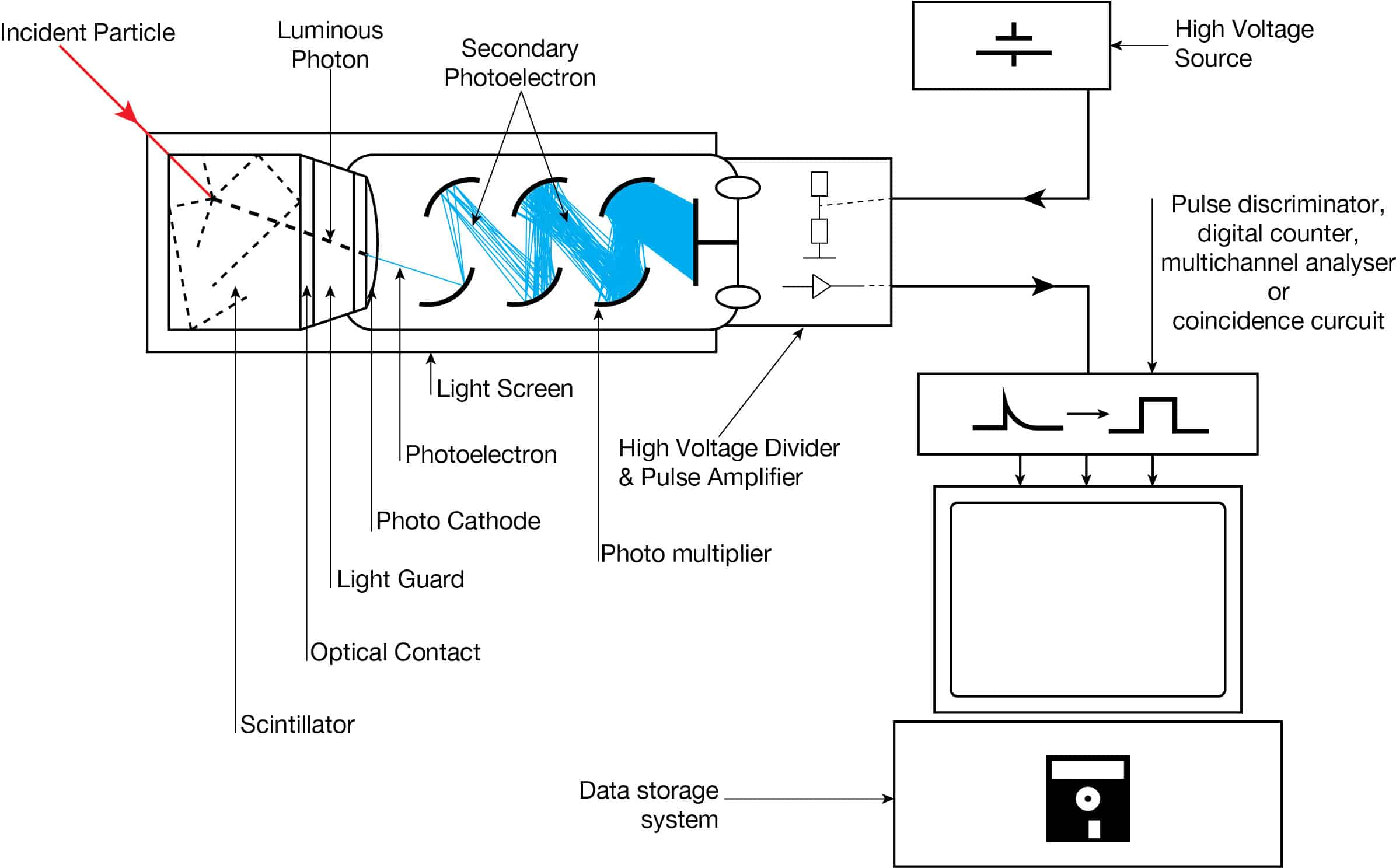
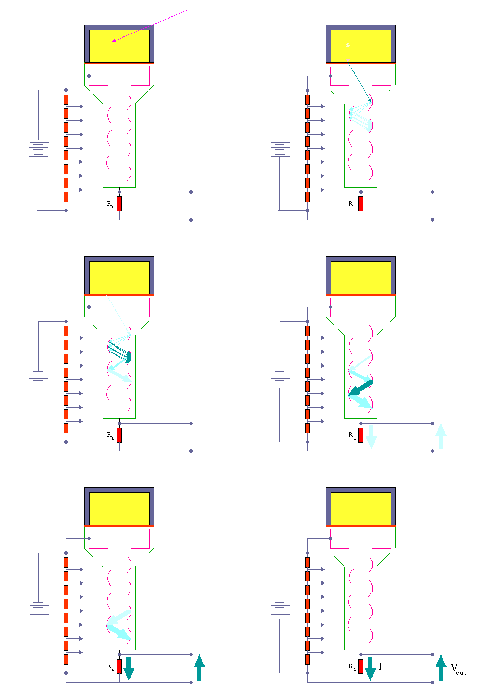
Apparatus with a scintillating crystal, photomultiplier, and data acquisition components. Source: wikipedia.org License CC BY-SA 3.0
A scintillation counter or scintillation detector is a radiation detector which uses the effect known as scintillation. Scintillation is a flash of light produced in a transparent material by the passage of a particle (an electron, an alpha particle, an ion, or a high-energy photon). Scintillation occurs in the scintillator, which is a key part of a scintillation detector. In general, a scintillation detector consists of:
Scintillator. A scintillator generates photons in response to incident radiation.
Photodetector. A sensitive photodetector (usually a photomultiplier tube (PMT), a charge-coupled device (CCD) camera, or a photodiode), which converts the light to an electrical signal and electronics to process this signal.
The basic principle of operation involves the radiation reacting with a scintillator, which produces a series of flashes of varying intensity. The intensity of the flashes is proportional to the energy of the radiation. This feature is very important. These counters are suited to measure the energy of gamma radiation (gamma spectroscopy) and, therefore, can be used to identify gamma emitting isotopes.
Scintillation counters are widely used in radiation protection, assay of radioactive materials and physics research because they can be made inexpensively yet with good efficiency, and can measure both the intensity and the energy of incident radiation. Hospitals all over the world have gamma cameras based on the scintillation effect and, therefore, they are also called scintillation cameras.
The advantages of a scintillation counter are its efficiency and the high precision and counting rates that are possible. These latter attributes are a consequence of the extremely short duration of the light flashes, from about 10-9 (organic scintillators) to 10-6 (inorganic scintillators) seconds. The intensity of the flashes and the amplitude of the output voltage pulse are proportional to the energy of the radiation. Therefore, scintillation counters can be used to determine the energy, as well as the number, of the exciting particles (or gamma photons). For gamma spectrometry, the most common detectors include sodium iodide (NaI) scintillation counters and high-purity germanium detectors.
Scintillation Counter – Principle of Operation
The operation of scintillation counters is summarized in the following points:
Scintillation Counter – Principle of Operation. Source: wikipedia.org License: Public Domain
Ionizing radiation enters the scintillator and interacts with the scintillator material. This cause electrons to be raised to an excited state.
For charged particles the track is the path of the particle itself.
The excited atoms of the scintillator material de-excite and rapidly emit a photon in the visible (or near-visible) light range. The quantity is proportional to the energy deposited by the ionizing particle. The material is said to fluoresce.
Three classes of phosphors are used:
inorganic crystals,
organic crystals,
plastic phosphors.
The light created in the scintillator strikes the photocathode of a photomultiplier tube, releasing at most one photoelectron per photon.
Using a voltage potential, this group of primary electrons is electrostatically accelerated and focused so that they strike the first dynode with enough energy to release additional electrons.
These secondary electrons are attracted and strike a second dynode releasing more electrons. This process occurs in the photomultiplier tube.
Each subsequent dynode impact releases further electrons, and so there is a current amplifying effect at each dynode stage. Each stage is at a higher potential than the previous to provide the accelerating field.
Primary signal is multiplied and this amplification continues through 10 to 12 stages.
At the final dynode, sufficient electrons are available to produce a pulse of sufficient magnitude for further amplification. This pulse carries information about the energy of the original incident radiation. The number of such pulses per unit time also gives information about the intensity of the radiation.
A scintillation detector or scintillation counter is obtained when a scintillator is coupled to an electronic light sensor such as:
a photomultiplier tube (PMT),
a charge-coupled device (CCD) camera,
photodiode
All these devices may be used in scintillation counters and all convert the light to an electrical signal and contain electronics to process this signal. A photomultiplier tube (PMT) absorbs the light emitted by the scintillator and re-emit it in the form of electrons via the photoelectric effect. The PMT has been the main choice for photon detection ever since due to the fact that they have high quantum efficiency and high amplification. Lately however semiconductors have begun to compete with the PMT, the photodiode, for example, which has higher quantum efficiency in the visible range and above, lower power consumption and smaller size.
Vacuum photodiodes are similar but do not amplify the signal while silicon photodiodes, on the other hand, detect incoming photons by the excitation of charge carriers directly in the silicon.
A number of portable gamma cameras for medical imaging use scintillator-CCD based detectors. In this case, a scintillator converts the incident radiation (X-rays usually) into visible wavelength photons, which can then be directly detected by the CCD camera.
Note, that the term quantum efficiency (QE) may apply to incident photon to converted electron (IPCE) ratio, of a photosensitive device. The quantum efficiency for the photodiode is high (60-80%) compared to the PMT (20-30%) which gives a higher energy resolution.
Scintillation Materials – Scintillators
Scintillators are kinds of materials that provide detectable photons in the visible part of the light spectrum, following the passage of a charged particle or a photon. The scintillator consists of a transparent crystal, usually a phosphor, plastic or organic liquid that fluoresces when struck by ionizing radiation. The scintillator must also be transparent to its own light emissions and it must have a short decay time. The scintillator must be also shielded from all ambient light so that external photons do not swamp the ionization events caused by incident radiation. To achieve this a thin opaque foil, such as aluminized mylar, is often used, though it must have a low enough mass to minimize undue attenuation of the incident radiation being measured.
There are primarily two types of scintillators in common use in nuclear and particle physics: organic or plastic scintillators and inorganic or crystalline scintillators.
Inorganic Scintillators
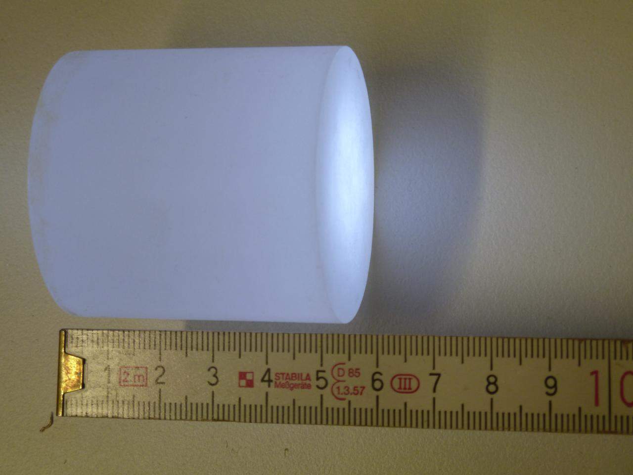
CsI(Tl) scintillation crystal. Source: wikipedia.de License: CC BY-SA 3.0
Inorganic scintillators are usually crystals grown in high temperature furnaces. They include lithium iodide (LiI), sodium iodide (NaI), cesium iodide (CsI), and zinc sulfide (ZnS). The most widely used scintillation material is NaI(Tl) (thallium-doped sodium iodide). The iodine provides most of the stopping power in sodium iodide (since it has a high Z = 53). These crystalline scintillators are characterized by high density, high atomic number, and pulse decay times of approximately 1 microsecond (~ 10-6 sec). Scintillation in inorganic crystals is typically slower than in organic ones. They exhibit high efficiency for detection of gamma rays and are capable of handling high count rates. Inorganic crystals can be cut to small sizes and arranged in an array configuration so as to provide position sensitivity. This feature is widely used in medical imaging to detect X-rays or gamma rays. Inorganic scintillators are better at detecting gamma rays and X-rays than organic scintillators. This is due to their high density and atomic number which gives a high electron density. A disadvantage of some inorganic crystals, e.g., NaI, is their hygroscopicity, a property which requires them to be housed in an airtight container to protect them from moisture.
The most widely used scintillation material is NaI(Tl) (thallium-doped sodium iodide). NaI(Tl) as the scintillator is used in scintillation detectors, traditionally in nuclear medicine, geophysics, nuclear physics, and environmental measurements. The iodine provides most of the stopping power in sodium iodide (since it has a high Z = 53). These crystalline scintillators are characterized by high density, high atomic number, and pulse decay times of approximately 1 microsecond (~ 10-6 sec). The wavelength of maximum emission is 415 nm. Scintillation in inorganic crystals is typically slower than in organic ones. They exhibit high efficiency for detection of gamma rays and are capable of handling high count rates. Inorganic crystals can be cut to small sizes and arranged in an array configuration so as to provide position sensitivity. This feature is widely used in medical imaging to detect X-rays or gamma rays. Inorganic scintillators are better at detecting gamma rays and X-rays. The NaI(Tl) scintillator has a higher energy resolution than a proportional counter, allowing for more accurate energy determinations. This is due to their high density and atomic number which gives a high electron density. A disadvantage of some inorganic crystals, e.g., NaI, is their hygroscopicity, a property which requires them to be housed in an airtight container to protect them from moisture. The crystals are usually coupled with a photomultiplier tube, in a hermetically sealed assembly.
Caesium iodide (CsI) in crystalline form is used as the scintillator for the detection of protons and alpha particles. Pure CsI is a fast and dense scintillating material with relatively low light yield that increases significantly with cooling. The drawbacks of CsI are a high temperature gradient and a slight hygroscopicity.
Thallium-doped Caesium Iodide has an effective atomic number of 54 and a density of 4.51 g/cm3. CsI(TI) is also hygroscopic and should not be subjected to high humidity or water. CsI(TI) has different decay times for different particles (680ns and 3340ns) and can be used to determine between different kinds of radiation. The emission spectrum is peaked at 540-560 nm.
Organic Scintillators
Organic scintillators are kinds of organic materials that provide detectable photons in the visible part of the light spectrum, following the passage of a charged particle or a photon. The scintillation mechanism in organic materials is quite different from the mechanism in inorganic crystals. In inorganic scintillators, e.g. NaI, CsI the scintillation arises because of the structure of the crystal lattice. The fluorescence mechanism in organic materials arises from transitions in the energy levels of a single molecule and therefore the fluorescence can be observed independently of the physical state (vapor, liquid, solid).
In general, organic scintillators have fast decay times (typically ~10-8 sec), while inorganic crystals are usually far slower (~10-6 sec), although some also have fast components in their response. There are three types of organic scintillators:
Pure organic crystals. Pure organic crystals include crystals of anthracene, stilbene and naphthalene. The decay time of this type of phosphor is approximately 10 nanoseconds. This type of crystal is frequently used in the detection of beta particles. They are very durable, but their response is anisotropic (which spoils energy resolution when the source is not collimated), and they cannot be easily machined, nor can they be grown in large sizes. Therefore they are not very often used.
Liquid organic solutions. Liquid organic solutions are produced by dissolving an organic scintillator in a solvent.
Plastic scintillators. Plastic phosphors are made by adding scintillation chemicals to a plastic matrix. The decay constant is the shortest of the three phosphor types, approaching 1 or 2 nanoseconds. Plastic scintillators are therefore more appropriate for use in high-flux environments and in high dose rate measurements. The plastic has a high hydrogen content, therefore, it is useful for fast neutron detectors. It takes substantially more energy to produce a detectable photon in a scintillator than an electron-ion pair through ionization (typically by a factor of 10), and because inorganic scintillators produce more light than organic scintillators, they are consequently better for applications at low energies.
Photomultiplier Tube
Photomultiplier tubes (PMTs) are a photon detection device that uses the photoelectric effect combined with secondary emission to convert light into an electrical signal. A photomultiplier absorbs light emitted by the scintillator and re-emit it in the form of electrons via the photoelectric effect. The PMT has been the main choice for photon detection ever since due to the fact that they have high quantum efficiency and high amplification.
Components of Photomultiplier Tube
The device consists of several components and these components are shown in the figure.
Apparatus with a scintillating crystal, photomultiplier, and data acquisition components. Source: wikipedia.org License CC BY-SA 3.0
Photocathode. Right after a thin entry window, is a photocathode, which is made of material in which the valence electrons are weakly bound and have a high cross section for converting photons to electrons via the photoelectric effect. For example, Cs3Sb (caesium-antimony) may be used. As a result, the light created in the scintillator strikes the photocathode of a photomultiplier tube, releasing at most one photoelectron per photon.
Dynodes. Using a voltage potential, this group of primary electrons is electrostatically accelerated and focused so that they strike the first dynode with enough energy to release additional electrons. There is a series (“stages”) of dynodes made of material of relatively low work function. These electrodes are operated at ever increasing potential (e.g. ~100-200 V between dynodes). At the dynode the electrons are multiplied by secondary emission. The next dynode has a higher voltage which makes the electrons released from the first to accelerate towards it. At each dynode 3-4 electrons are released for every incident electron, and with 6 to 14 dynodes the total gain, or electron amplification factor, will be in the range of ~104-107 when they reach the anode. Typical operating voltages are in the range of 500 to 3000 V. At the final dynode, sufficient electrons are available to produce a pulse of sufficient magnitude for further amplification. This pulse carries information about the energy of the original incident radiation. The number of such pulses per unit time also gives information about the intensity of the radiation.
Quantum Efficiency
The sensitivity of a photocathode is usually quoted in terms of the quantum efficiency. In general, the term quantum efficiency (QE) may apply to incident photon to converted electron (IPCE) ratio of a photosensitive device. The quantum efficiency of the photocathode is defined as the probability for the conversion of incident photons to an electrical signal and is defined as:
The quantum efficiency of any photosensitive device is a strong function of wavelength of the incident light, and an effort is made to match the spectral response of the photocathode to the emission spectrum of the scintillator in use. In the photomultiplier tube the quantum efficiency is limited to 20-30%, but an average quantum efficiency over the emission spectrum of a typical scintillator is about 15-20%.
The standard for quotation is the number of photoelectrons per keV energy loss by fast electrons in a NaI(Tl) scintillator. For the peak quantum efficiency, about 8 ~ 10 photoelectrons are produced per each keV energy loss. Therefore, the average energy loss required to create a single photoelectron is ~ 100 eV, which is much bigger than the values in gas-filled detectors or semiconductor detectors.
The PMT has been the main choice for photon detection ever since due to the fact that they have high quantum efficiency and high amplification. Lately however semiconductors have begun to compete with the PMT, the photodiode for example which has higher quantum efficiency in the visible range and above, lower power consumption and smaller size. The quantum efficiency for the photodiode is high (60-80%) compared to the PMT (20-30%) which gives a higher energy resolution.
Photodiodes – Scintillation Counter
A scintillation detector or scintillation counter is obtained when a scintillator is coupled to an electronic light sensor such as:
a photomultiplier tube (PMT),
a charge-coupled device (CCD) camera,
photodiode
All these devices may be used in scintillation counters and all convert the light to an electrical signal and contain electronics to process this signal. A photodiode is a semiconductor device that converts light into an electrical current. This is a semiconductor device which consists of a thin layer of silicon in which the light is absorbed after which free charge carriers (electrons and holes) are created. A conventional photodiode most often refers to a PIN diode. PIN means that the p and the n doped sides are separated by a depleted i-region. Electrons and holes are collected at the anode and cathode of the diode. This results in a photocurrent that is the output of the diode. The charge is however not amplified making the output signal amplitude small. This makes the photodiode sensitive to electronic noise. On the other hand, the quantum efficiency for the photodiode is high (60-80%) compared to the PMT (20-30%) which gives a higher energy resolution.
Detection of Alpha, Beta and Gamma Radiation using Scintillation Counter
Scintillation counters are used to measure radiation in a variety of applications including hand held radiation survey meters, personnel and environmental monitoring for radioactive contamination, medical imaging, radiometric assay, nuclear security and nuclear plant safety. They are widely used because they can be made inexpensively yet with good efficiency, and can measure both the intensity and the energy of incident radiation.
Alpha Particles and Heavy Ions. Due to the very high ionizing power of heavy ions, scintillation counters are usually not ideal for the detection of heavy ions. For equal energies, a proton will produce 1/4 to 1/2 the light of an electron, while alpha particles will produce only about 1/10 the light. Where needed, inorganic crystals, e.g. CsI(Tl), ZnS(Ag) (typically used in thin sheets as α-particle monitors), should be preferred to organic materials. Pure CsI is a fast and dense scintillating material with relatively low light yield that increases significantly with cooling. The drawbacks of CsI are a high temperature gradient and a slight hygroscopicity.
Beta Particles. For detection of beta particles, organic scintillators can be used. Pure organic crystals include crystals of anthracene, stilbene and naphthalene. The decay time of this type of phosphor is approximately 10 nanoseconds. This type of crystal is frequently used in the detection of beta particles. Organic scintillators, having a lower Z than inorganic crystals, are best suited for the detection of low-energy (< 10 MeV) beta particles.
Gamma Rays. High-Z materials are best suited as scintillators for the detection of gamma rays. The most widely used scintillation material is NaI(Tl) (thallium-doped sodium iodide). The iodine provides most of the stopping power in sodium iodide (since it has a high Z = 53). These crystalline scintillators are characterized by high density, high atomic number, and pulse decay times of approximately 1 microsecond (~ 10-6 sec). Scintillation in inorganic crystals is typically slower than in organic ones. They exhibit high efficiency for detection of gamma rays and are capable of handling high count rates. Inorganic crystals can be cut to small sizes and arranged in an array configuration so as to provide position sensitivity. This feature is widely used in medical imaging to detect X-rays or gamma rays. Inorganic scintillators are better at detecting gamma rays and X-rays. This is due to their high density and atomic number which gives a high electron density.
Neutrons. Since the neutrons are electrically neutral particles, they are mainly subject to strong nuclear forces but not to electric forces. Therefore neutrons are not directly ionizing and they have usually to be converted into charged particles before they can be detected. Generally every type of neutron detector must be equipped with converter (to convert neutron radiation to common detectable radiation) and one of the conventional radiation detectors (scintillation detector, gaseous detector, semiconductor detector, etc.). Fast neutrons (>0.5 MeV) primarily rely on the recoil proton in (n,p) reactions. Materials rich in hydrogen, for example plastic scintillators, are therefore best suited for their detection. Thermal neutrons rely on nuclear reactions such as the (n,γ) or (n,α) reactions, to produce ionization. Materials such as LiI(Eu) or glass silicates are therefore particularly well-suited for the detection of thermal neutrons.
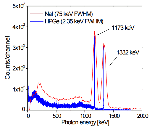
In general, gamma spectroscopy is the study of the energy spectra of gamma ray sources, such as in the nuclear industry, geochemical investigation, and astrophysics. Spectroscopes, or spectrometers, are sophisticated devices designed to measure the spectral power distribution of a source. The incident radiation generates a signal that allows to determine the energy of the incident particle.
Figure: Caption: Comparison of NaI(Tl) and HPGe spectra for cobalt-60. Source: Radioisotopes and Radiation Methodology I, II. Soo Hyun Byun, Lecture Notes. McMaster University, Canada.
Most radioactive sources produce gamma rays, which are of various energies and intensities. Gamma rays frequently accompany the emission of alpha and beta radiation. When these emissions are detected and analyzed with a spectroscopy system, a gamma-ray energy spectrum can be produced. Gamma rays from radioactive decay are in the energy range from a few keV to ~8 MeV, corresponding to the typical energy levels in nuclei with reasonably long lifetimes. As was written, they are produced by the decay of nuclei as they transition from a high energy state to a lower state. A detailed analysis of this spectrum is typically used to determine the identity and quantity of gamma emitters present in a sample, and is a vital tool in radiometric assay. The gamma spectrum is characteristic of the gamma-emitting nuclides contained in the source.
Robert Reed Burn, Introduction to Nuclear Reactor Operation, 1988.
U.S. Department of Energy, Nuclear Physics and Reactor Theory. DOE Fundamentals Handbook, Volume 1 and 2. January 1993.
Paul Reuss, Neutron Physics. EDP Sciences, 2008. ISBN: 978-2759800414.
See also:
Detection
We hope, this article, Scintillation Counter – Scintillation Detector, helps you. If so, give us a like in the sidebar. Main purpose of this website is to help the public to learn some interesting and important information about radiation and dosimeters.
Fast neutrons have kinetic energies greater than 1 MeV (~15 000 km/s) and are also named fission neutrons. These neutrons are produced by nuclear processes such as nuclear fission or (ɑ,n) reactions. Radiation Dosimetry
Free neutrons can be classified according to their kinetic energy. This energy is usually given in electron volts (eV). The term temperature can also describe this energy representing thermal equilibrium between a neutron and a medium with a certain temperature.
Kinetic Energies of Neutrons – Fast Neutrons
Cold Neutrons (0 eV; 0.025 eV). Neutrons in thermal equilibrium with very cold surroundings such as liquid deuterium. This spectrum is used for neutron scattering experiments.
Thermal Neutrons. Neutrons in thermal equilibrium with a surrounding medium. Most probable energy at 20°C (68°F) for Maxwellian distribution is 0.025 eV (~2 km/s). This part of neutron’s energy spectrum constitutes most important part of spectrum in thermal reactors.
Epithermal Neutrons (0.025 eV; 0.4 eV). Neutrons of kinetic energy greater than thermal. Some of reactor designs operates with epithermal neutron’s spectrum. This design allows to reach higher fuel breeding ratio than in thermal reactors.
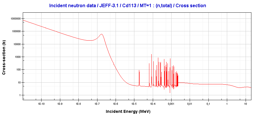
Neutrons of kinetic energy below the cadmium cut-off energy (~0.5 eV) are strongly absorbed by 113-Cd. Source: JANIS (Java-based nuclear information software) www.oecd-nea.org/janis/
Cadmium Neutrons (0.4 eV; 0.5 eV). Neutrons of kinetic energy below the cadmium cut-off energy. One cadmium isotope, 113Cd, absorbs neutrons strongly only if they are below ~0.5 eV (cadmium cut-off energy).
Epicadmium Neutrons (0.5 eV; 1 eV). Neutrons of kinetic energy above the cadmium cut-off energy. These neutrons are not absorbed by cadmium.
Slow Neutrons (1 eV; 10 eV).
Resonance Neutrons (10 eV; 300 eV). The resonance neutrons are called resonance for their special bahavior. At resonance energies the cross-sectionscan reach peaks more than 100x higher as the base value of cross-section. At this energies the neutron capture significantly exceeds a probability of fission. Therefore it is very important (for thermal reactors) to quickly overcome this range of energy and operate the reactor with thermal neutrons resulting in increase of probability of fission.
Intermediate Neutrons (300 eV; 1 MeV).
Fast Neutrons (1 MeV; 20 MeV). Neutrons of kinetic energy greater than 1 MeV (~15 000 km/s) are usually named fission neutrons. These neutrons are produced by nuclear processes such as nuclear fission or (ɑ,n) reactions. The fission neutrons have a Maxwell-Boltzmann distribution of energy with a mean energy (for 235U fission) 2 MeV. Inside a nuclear reactor the fast neutrons are slowed down to the thermal energies via a process called neutron moderation.
Relativistic Neutrons (20 MeV; ->)
The reactor physics does not need this fine division of neutron energies. The neutrons can be roughly (for purposes of reactor physics) divided into three energy ranges:
Thermal neutrons (0.025 eV – 1 eV).
Resonance neutrons (1 eV – 1 keV).
Fast neutrons (1 keV – 10 MeV).
Even most of reactor computing codes use only two neutron energy groups:
From the physics point of view, the main differences among reactor types arise from differences in their neutron energy spectra. In fact, the basic classification of nuclear reactors is based upon the average energy of the neutrons which cause the bulk of the fissions in the reactor core. From this point of view nuclear reactors are divided into two categories:
Thermal Reactors. Almost all of the current reactors which have been built to date use thermal neutronsto sustain the chain reaction. These reactors contain neutron moderator that slows neutrons from fission until their kinetic energy is more or less in thermal equilibrium with the atoms (E < 1 eV) in the system.
Fast Neutron Reactors. Fast reactors containsno neutron moderator and use less-moderating primary coolants, because they use fast neutrons (E > 1 keV), to cause fission in their fuel.
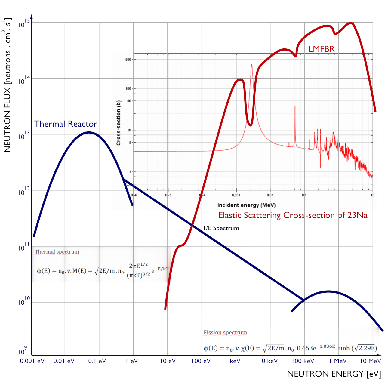
Comparison of neutron spectra in a typical LWR and asodium-cooled fast breeder reactor. Note that, the fast reactor spectrum is highly affected by the elastic scattering cross-section of used coolant.
The main differences between these two types are, of course, in neutron cross-sections, that exhibit significant energy dependency. It can be characterized by capture-to-fission ratio, which is lower in fast reactors. There is also a difference in the number of neutrons produced per one fission, which is higher in fast reactors than in thermal reactors. These very important differences are caused primarily by differences in neutron fluxes. Therefore it is very important to know detailed neutron energy distribution in a reactor core.
Detection of Neutrons using Ionization Chamber
Since the neutrons are electrically neutral particles, they are mainly subject to strong nuclear forces but not to electric forces. Therefore neutrons are not directly ionizing and they have usually to be converted into charged particles before they can be detected. Generally every type of neutron detector must be equipped with converter (to convert neutron radiation to common detectable radiation) and one of the conventional radiation detectors (scintillation detector, gaseous detector, semiconductor detector, etc.).
Ionization chambers are often used as the charged particle detection device. For example, if the inner surface of the ionization chamber is coated with a thin coat of boron, the (n,alpha) reaction can take place. Most of (n,alpha) reactions of thermal neutrons are 10B(n,alpha)7Li reactions accompanied by 0.48 MeV gamma emission.
Moreover, isotope boron-10 has high (n,alpha) reaction cross-section along the entire neutron energy spectrum. The alpha particle causes ionization within the chamber, and ejected electrons cause further secondary ionizations.
Another method for detecting neutrons using an ionization chamber is to use the gas boron trifluoride (BF3) instead of air in the chamber. The incoming neutrons produce alpha particles when they react with the boron atoms in the detector gas. Either method may be used to detect neutrons in nuclear reactor. It must be noted, BF3 counters are usually operated in the proportional region.
Detection of Neutrons using Scintillation Counter
Since the neutrons are electrically neutral particles, they are mainly subject to strong nuclear forces but not to electric forces. Therefore neutrons are not directly ionizing and they have usually to be converted into charged particles before they can be detected. Generally every type of neutron detector must be equipped with converter (to convert neutron radiation to common detectable radiation) and one of the conventional radiation detectors (scintillation detector, gaseous detector, semiconductor detector, etc.). Fast neutrons (>0.5 MeV) primarily rely on the recoil proton in (n,p) reactions. Materials rich in hydrogen, for example plastic scintillators, are therefore best suited for their detection. Thermal neutrons rely on nuclear reactions such as the (n,γ) or (n,α) reactions, to produce ionization. Materials such as LiI(Eu) or glass silicates are therefore particularly well-suited for the detection of thermal neutrons.
Robert Reed Burn, Introduction to Nuclear Reactor Operation, 1988.
U.S. Department of Energy, Nuclear Physics and Reactor Theory. DOE Fundamentals Handbook, Volume 1 and 2. January 1993.
Paul Reuss, Neutron Physics. EDP Sciences, 2008. ISBN: 978-2759800414.
See also:
Neutron
We hope, this article, Fast Neutron – High-Energy Neutron, helps you. If so, give us a like in the sidebar. Main purpose of this website is to help the public to learn some interesting and important information about radiation and dosimeters.
Scintillation is a flash of light produced in a transparent material by the passage of a particle (an electron, an alpha particle, an ion, or a high-energy photon). Scintillation occurs in the scintillator, which is a key part of a scintillation detector. Radiation Dosimetry
Apparatus with a scintillating crystal, photomultiplier, and data acquisition components. Source: wikipedia.org License CC BY-SA 3.0
Scintillation is a flash of light produced in a transparent material by the passage of a particle (an electron, an alpha particle, an ion, or a high-energy photon). Scintillation occurs in the scintillator, which is a key part of a scintillation detector. In general, a scintillation detector consists of:
Scintillator. A scintillator generates photons in response to incident radiation.
Photodetector. A sensitive photodetector (usually a photomultiplier tube (PMT), a charge-coupled device (CCD) camera, or a photodiode), which converts the light to an electrical signal and electronics to process this signal.
Scintillation Materials – Scintillators
Scintillators are kinds of materials that provide detectable photons in the visible part of the light spectrum, following the passage of a charged particle or a photon. The scintillator consists of a transparent crystal, usually a phosphor, plastic or organic liquid that fluoresces when struck by ionizing radiation. The scintillator must also be transparent to its own light emissions and it must have a short decay time. The scintillator must be also shielded from all ambient light so that external photons do not swamp the ionization events caused by incident radiation. To achieve this a thin opaque foil, such as aluminized mylar, is often used, though it must have a low enough mass to minimize undue attenuation of the incident radiation being measured.
There are primarily two types of scintillators in common use in nuclear and particle physics: organic or plastic scintillators and inorganic or crystalline scintillators.
Inorganic Scintillators
CsI(Tl) scintillation crystal. Source: wikipedia.de License: CC BY-SA 3.0
Inorganic scintillators are usually crystals grown in high temperature furnaces. They include lithium iodide (LiI), sodium iodide (NaI), cesium iodide (CsI), and zinc sulfide (ZnS). The most widely used scintillation material is NaI(Tl) (thallium-doped sodium iodide). The iodine provides most of the stopping power in sodium iodide (since it has a high Z = 53). These crystalline scintillators are characterized by high density, high atomic number, and pulse decay times of approximately 1 microsecond (~ 10-6 sec). Scintillation in inorganic crystals is typically slower than in organic ones. They exhibit high efficiency for detection of gamma rays and are capable of handling high count rates. Inorganic crystals can be cut to small sizes and arranged in an array configuration so as to provide position sensitivity. This feature is widely used in medical imaging to detect X-rays or gamma rays. Inorganic scintillators are better at detecting gamma rays and X-rays than organic scintillators. This is due to their high density and atomic number which gives a high electron density. A disadvantage of some inorganic crystals, e.g., NaI, is their hygroscopicity, a property which requires them to be housed in an airtight container to protect them from moisture.
The most widely used scintillation material is NaI(Tl) (thallium-doped sodium iodide). NaI(Tl) as the scintillator is used in scintillation detectors, traditionally in nuclear medicine, geophysics, nuclear physics, and environmental measurements. The iodine provides most of the stopping power in sodium iodide (since it has a high Z = 53). These crystalline scintillators are characterized by high density, high atomic number, and pulse decay times of approximately 1 microsecond (~ 10-6 sec). The wavelength of maximum emission is 415 nm. Scintillation in inorganic crystals is typically slower than in organic ones. They exhibit high efficiency for detection of gamma rays and are capable of handling high count rates. Inorganic crystals can be cut to small sizes and arranged in an array configuration so as to provide position sensitivity. This feature is widely used in medical imaging to detect X-rays or gamma rays. Inorganic scintillators are better at detecting gamma rays and X-rays. This is due to their high density and atomic number which gives a high electron density. A disadvantage of some inorganic crystals, e.g., NaI, is their hygroscopicity, a property which requires them to be housed in an airtight container to protect them from moisture. The crystals are usually coupled with a photomultiplier tube, in a hermetically sealed assembly.
Caesium iodide (CsI) in crystalline form is used as the scintillator for the detection of protons and alpha particles. Pure CsI is a fast and dense scintillating material with relatively low light yield that increases significantly with cooling. The drawbacks of CsI are a high temperature gradient and a slight hygroscopicity.
Thallium-doped Caesium Iodide has an effective atomic number of 54 and a density of 4.51 g/cm3. CsI(TI) is also hygroscopic and should not be subjected to high humidity or water. CsI(TI) has different decay times for different particles (680ns and 3340ns) and can be used to determine between different kinds of radiation. The emission spectrum is peaked at 540-560 nm.
Organic Scintillators
Organic scintillators are kinds of organic materials that provide detectable photons in the visible part of the light spectrum, following the passage of a charged particle or a photon. The scintillation mechanism in organic materials is quite different from the mechanism in inorganic crystals. In inorganic scintillators, e.g. NaI, CsI the scintillation arises because of the structure of the crystal lattice. The fluorescence mechanism in organic materials arises from transitions in the energy levels of a single molecule and therefore the fluorescence can be observed independently of the physical state (vapor, liquid, solid).
In general, organic scintillators have fast decay times (typically ~10-8 sec), while inorganic crystals are usually far slower (~10-6 sec), although some also have fast components in their response. There are three types of organic scintillators:
Pure organic crystals. Pure organic crystals include crystals of anthracene, stilbene and naphthalene. The decay time of this type of phosphor is approximately 10 nanoseconds. This type of crystal is frequently used in the detection of beta particles. They are very durable, but their response is anisotropic (which spoils energy resolution when the source is not collimated), and they cannot be easily machined, nor can they be grown in large sizes. Therefore they are not very often used.
Liquid organic solutions. Liquid organic solutions are produced by dissolving an organic scintillator in a solvent.
Plastic scintillators. Plastic phosphors are made by adding scintillation chemicals to a plastic matrix. The decay constant is the shortest of the three phosphor types, approaching 1 or 2 nanoseconds. Plastic scintillators are therefore more appropriate for use in high-flux environments and in high dose rate measurements. The plastic has a high hydrogen content, therefore, it is useful for fast neutron detectors. It takes substantially more energy to produce a detectable photon in a scintillator than an electron-ion pair through ionization (typically by a factor of 10), and because inorganic scintillators produce more light than organic scintillators, they are consequently better for applications at low energies.
Robert Reed Burn, Introduction to Nuclear Reactor Operation, 1988.
U.S. Department of Energy, Nuclear Physics and Reactor Theory. DOE Fundamentals Handbook, Volume 1 and 2. January 1993.
Paul Reuss, Neutron Physics. EDP Sciences, 2008. ISBN: 978-2759800414.
See also:
Scintillation Counters
We hope, this article, Scintillation, helps you. If so, give us a like in the sidebar. Main purpose of this website is to help the public to learn some interesting and important information about radiation and dosimeters.
Scintillators are kinds of materials, usually a transparent crystal, that provide detectable photons in the visible part of the light spectrum, following the passage of a charged particle or a photon. Radiation Dosimetry
Scintillation Materials – Scintillators
Scintillators are kinds of materials that provide detectable photons in the visible part of the light spectrum, following the passage of a charged particle or a photon. The scintillator consists of a transparent crystal, usually a phosphor, plastic or organic liquid that fluoresces when struck by ionizing radiation. The scintillator must also be transparent to its own light emissions and it must have a short decay time. The scintillator must be also shielded from all ambient light so that external photons do not swamp the ionization events caused by incident radiation. To achieve this a thin opaque foil, such as aluminized mylar, is often used, though it must have a low enough mass to minimize undue attenuation of the incident radiation being measured.
There are primarily two types of scintillators in common use in nuclear and particle physics: organic or plastic scintillators and inorganic or crystalline scintillators.
Inorganic Scintillators
CsI(Tl) scintillation crystal. Source: wikipedia.de License: CC BY-SA 3.0
Inorganic scintillators are usually crystals grown in high temperature furnaces. They include lithium iodide (LiI), sodium iodide (NaI), cesium iodide (CsI), and zinc sulfide (ZnS). The most widely used scintillation material is NaI(Tl) (thallium-doped sodium iodide). The iodine provides most of the stopping power in sodium iodide (since it has a high Z = 53). These crystalline scintillators are characterized by high density, high atomic number, and pulse decay times of approximately 1 microsecond (~ 10-6 sec). Scintillation in inorganic crystals is typically slower than in organic ones. They exhibit high efficiency for detection of gamma rays and are capable of handling high count rates. Inorganic crystals can be cut to small sizes and arranged in an array configuration so as to provide position sensitivity. This feature is widely used in medical imaging to detect X-rays or gamma rays. Inorganic scintillators are better at detecting gamma rays and X-rays than organic scintillators. This is due to their high density and atomic number which gives a high electron density. A disadvantage of some inorganic crystals, e.g., NaI, is their hygroscopicity, a property which requires them to be housed in an airtight container to protect them from moisture.
Apparatus with a scintillating crystal, photomultiplier, and data acquisition components. Source: wikipedia.org License CC BY-SA 3.0
The most widely used scintillation material is NaI(Tl) (thallium-doped sodium iodide). NaI(Tl) as the scintillator is used in scintillation detectors, traditionally in nuclear medicine, geophysics, nuclear physics, and environmental measurements. The iodine provides most of the stopping power in sodium iodide (since it has a high Z = 53). These crystalline scintillators are characterized by high density, high atomic number, and pulse decay times of approximately 1 microsecond (~ 10-6 sec). The wavelength of maximum emission is 415 nm. Scintillation in inorganic crystals is typically slower than in organic ones. They exhibit high efficiency for detection of gamma rays and are capable of handling high count rates. Inorganic crystals can be cut to small sizes and arranged in an array configuration so as to provide position sensitivity. This feature is widely used in medical imaging to detect X-rays or gamma rays. Inorganic scintillators are better at detecting gamma rays and X-rays. This is due to their high density and atomic number which gives a high electron density. A disadvantage of some inorganic crystals, e.g., NaI, is their hygroscopicity, a property which requires them to be housed in an airtight container to protect them from moisture. The crystals are usually coupled with a photomultiplier tube, in a hermetically sealed assembly.
Caesium iodide (CsI) in crystalline form is used as the scintillator for the detection of protons and alpha particles. Pure CsI is a fast and dense scintillating material with relatively low light yield that increases significantly with cooling. The drawbacks of CsI are a high temperature gradient and a slight hygroscopicity.
Thallium-doped Caesium Iodide has an effective atomic number of 54 and a density of 4.51 g/cm3. CsI(TI) is also hygroscopic and should not be subjected to high humidity or water. CsI(TI) has different decay times for different particles (680ns and 3340ns) and can be used to determine between different kinds of radiation. The emission spectrum is peaked at 540-560 nm.
Organic Scintillators
Organic scintillators are kinds of organic materials that provide detectable photons in the visible part of the light spectrum, following the passage of a charged particle or a photon. The scintillation mechanism in organic materials is quite different from the mechanism in inorganic crystals. In inorganic scintillators, e.g. NaI, CsI the scintillation arises because of the structure of the crystal lattice. The fluorescence mechanism in organic materials arises from transitions in the energy levels of a single molecule and therefore the fluorescence can be observed independently of the physical state (vapor, liquid, solid).
In general, organic scintillators have fast decay times (typically ~10-8 sec), while inorganic crystals are usually far slower (~10-6 sec), although some also have fast components in their response. There are three types of organic scintillators:
Pure organic crystals. Pure organic crystals include crystals of anthracene, stilbene and naphthalene. The decay time of this type of phosphor is approximately 10 nanoseconds. This type of crystal is frequently used in the detection of beta particles. They are very durable, but their response is anisotropic (which spoils energy resolution when the source is not collimated), and they cannot be easily machined, nor can they be grown in large sizes. Therefore they are not very often used.
Liquid organic solutions. Liquid organic solutions are produced by dissolving an organic scintillator in a solvent.
Plastic scintillators. Plastic phosphors are made by adding scintillation chemicals to a plastic matrix. The decay constant is the shortest of the three phosphor types, approaching 1 or 2 nanoseconds. Plastic scintillators are therefore more appropriate for use in high-flux environments and in high dose rate measurements. The plastic has a high hydrogen content, therefore, it is useful for fast neutron detectors. It takes substantially more energy to produce a detectable photon in a scintillator than an electron-ion pair through ionization (typically by a factor of 10), and because inorganic scintillators produce more light than organic scintillators, they are consequently better for applications at low energies.
Robert Reed Burn, Introduction to Nuclear Reactor Operation, 1988.
U.S. Department of Energy, Nuclear Physics and Reactor Theory. DOE Fundamentals Handbook, Volume 1 and 2. January 1993.
Paul Reuss, Neutron Physics. EDP Sciences, 2008. ISBN: 978-2759800414.
See also:
Scintillation Counters
We hope, this article, Scintillation Material – Types of Scintillators, helps you. If so, give us a like in the sidebar. Main purpose of this website is to help the public to learn some interesting and important information about radiation and dosimeters.
In the limited proportional region, the gas amplification factor does not continue to increase proportionally to the voltage. This region is usually avoided as a detection region. Radiation Dosimetry
The relationship between the applied voltage and pulse height in a detector is very complex. Pulse height and the number of ion pairs collected are directly related. As was written, the voltages can vary widely depending upon the detector geometry and the gas type and pressure. The figure schematically indicates the different voltage regions for alpha, beta and gamma rays. There are six main practical operating regions, where three (ionization, proportional and Geiger-Mueller region) are useful to detect ionizing radiation. These reqions are shown below. The alpha curve is higher than the beta and gamma curve from recombination region to part of limited proportionality region due to the larger number of ion pairs produced by the initial reaction of the incident radiation.
This diagram shows the number of ion pairs generated in the gas-filled detector, which varies according to the applied voltage for constant incident radiation. The voltages can vary widely depending upon the detector geometry and the gas type and pressure. This figure schematically indicates the different voltage regions for alpha, beta and gamma rays. There are six main practical operating regions, where three (ionization, proportional and Geiger-Mueller region) are useful to detect ionizing radiation. Alpha particles are more ionising than beta particles and than gamma rays, so more current is produced in the ion chamber region by alpha than beta and gamma, but the particles cannot be differentiated. More current is produced in the proportional counting region by alpha particles than beta, but by the nature of proportional counting it is possible to differentiate alpha, beta and gamma pulses. In the Geiger region, there is no differentiation of alpha and beta as any single ionisation event in the gas results in the same current output.
Limited Proportional Region
In the limited proportional region, the gas amplification factor does not continue to increase proportionally to the voltage. Additional ionizations and nonlinear effects causes, that there is no proportionality of the output signal to the deposited energy at a given applied voltage. The electric field in the chamber is distorted due to the high positive ion concentration. Free electrons are much lighter than the positive ions, thus, they are drawn toward the positive central electrode much faster than the positive ions are drawn to the chamber wall. The resulting cloud of positive ions near the electrode leads to distortions in gas multiplication. This region is usually avoided as a detection region.
Robert Reed Burn, Introduction to Nuclear Reactor Operation, 1988.
U.S. Department of Energy, Nuclear Physics and Reactor Theory. DOE Fundamentals Handbook, Volume 1 and 2. January 1993.
Paul Reuss, Neutron Physics. EDP Sciences, 2008. ISBN: 978-2759800414.
See also:
Gaseous Detectors
We hope, this article, Limited Proportional Region – Ionization Detector, helps you. If so, give us a like in the sidebar. Main purpose of this website is to help the public to learn some interesting and important information about radiation and dosimeters.
In the Geiger-Mueller region, the voltage and thus the electric field is so strong that secondary avalanches can occur. These avalanches can be triggered and propagated by photons emitted by atoms excited in the original avalanche. Radiation Dosimetry
Detector of Ionizing Radiation – Geiger Tube
The relationship between the applied voltage and pulse height in a detector is very complex. Pulse height and the number of ion pairs collected are directly related. As was written, the voltages can vary widely depending upon the detector geometry and the gas type and pressure. The figure schematically indicates the different voltage regions for alpha, beta and gamma rays. There are six main practical operating regions, where three (ionization, proportional and Geiger-Mueller region) are useful to detect ionizing radiation. These reqions are shown below. The alpha curve is higher than the beta and gamma curve from recombination region to part of limited proportionality region due to the larger number of ion pairs produced by the initial reaction of the incident radiation.
This diagram shows the number of ion pairs generated in the gas-filled detector, which varies according to the applied voltage for constant incident radiation. The voltages can vary widely depending upon the detector geometry and the gas type and pressure. This figure schematically indicates the different voltage regions for alpha, beta and gamma rays. There are six main practical operating regions, where three (ionization, proportional and Geiger-Mueller region) are useful to detect ionizing radiation. Alpha particles are more ionising than beta particles and than gamma rays, so more current is produced in the ion chamber region by alpha than beta and gamma, but the particles cannot be differentiated. More current is produced in the proportional counting region by alpha particles than beta, but by the nature of proportional counting it is possible to differentiate alpha, beta and gamma pulses. In the Geiger region, there is no differentiation of alpha and beta as any single ionisation event in the gas results in the same current output.Visualisation of the spread of Townsend avalanches by means of UV photons. Source: wikpedia.org License: CC BY-SA 3.0
Geiger-Mueller Region
In the Geiger-Mueller region, the voltage and thus the electric field is so strong that secondary avalanches can occur. These avalanches can be triggered and propagated by photons emitted by atoms excited in the original avalanche. Since these photons are not affected by the electric field, they may interact far (e.g. laterally to the axis) from the primary avalanche, the entire Geiger tube is participating in the process. A strong signal (the amplification factor can reach about 1010) is produced by these avalanches with shape and height independently of the primary ionization and the energy of the detected photon. Detectors, which are operated in the Geiger-Mueller region, are capable of detection of gamma rays, and also of all types of charged particles, that can enter the detector. These detectors are known as Geiger counters. Main advantage of these instruments is that they usually do not require any signal amplifiers. Since the positive ions do not move far from the avalanche region, a positively charged ion cloud disturbs the electric field and terminates the avalanche process. In practice the termination of the avalanche is improved by the use of “quenching” techniques. In contrast to proportional counters the energy or even incident radiation particle cannot not be distinguished by Geiger counters, since the output signal is independent of the amount and type of original ionization.
Robert Reed Burn, Introduction to Nuclear Reactor Operation, 1988.
U.S. Department of Energy, Nuclear Physics and Reactor Theory. DOE Fundamentals Handbook, Volume 1 and 2. January 1993.
Paul Reuss, Neutron Physics. EDP Sciences, 2008. ISBN: 978-2759800414.
See also:
Gaseous Detectors
We hope, this article, Geiger-Mueller Region – Ionization Detector, helps you. If so, give us a like in the sidebar. Main purpose of this website is to help the public to learn some interesting and important information about radiation and dosimeters.