Cloud chambers, also known as Wilson cloud chambers, are particle detectors, that were essential devices in early nuclear and particle physics research. Radiation Dosimetry
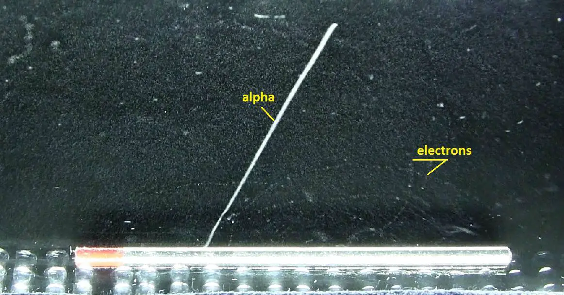
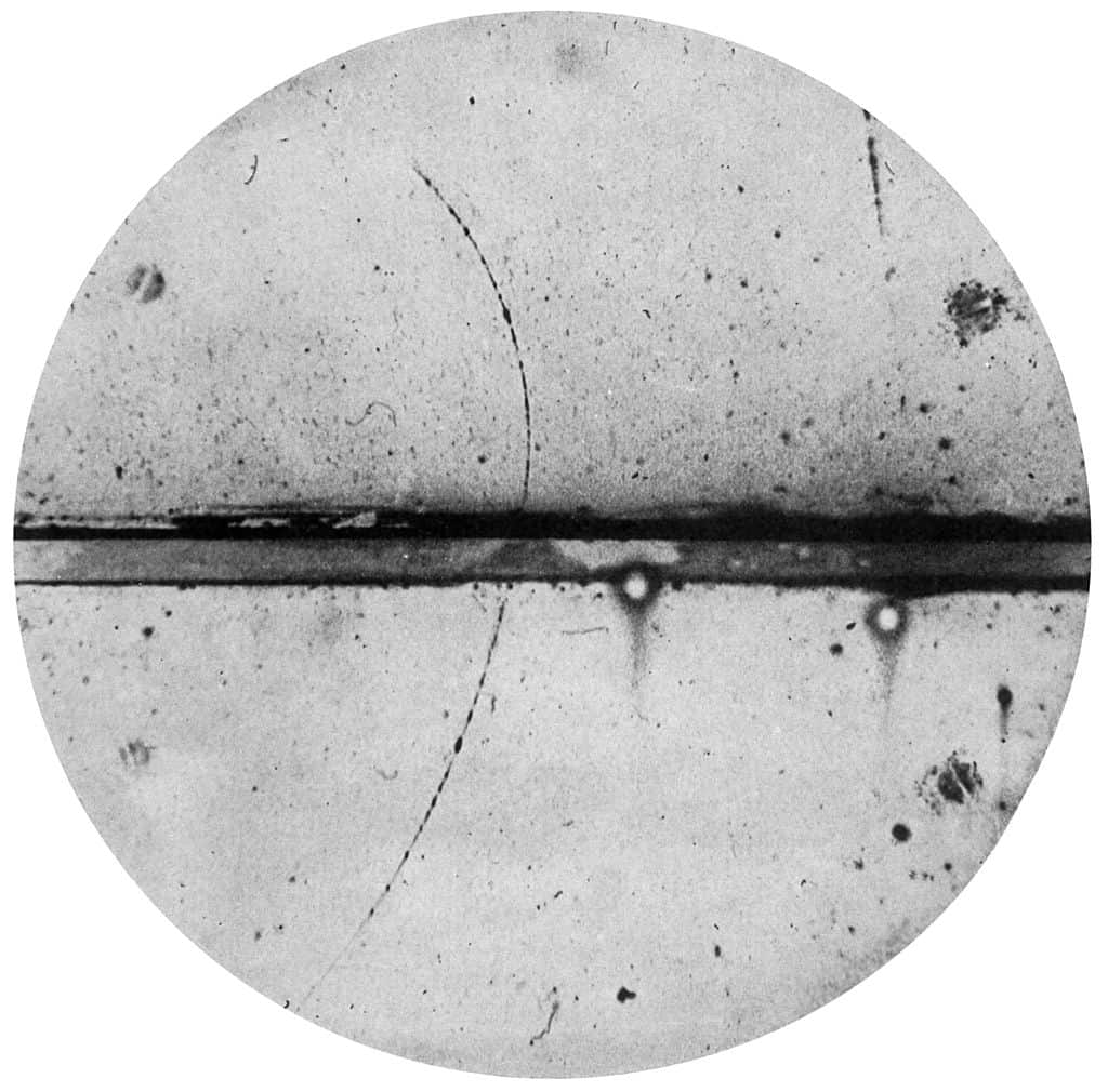
Alpha particles and electrons (deflected by a magnetic field) from a thorium rod in a cloud chamber. Source: wikipedia.org
Cloud chambers, also known as Wilson cloud chambers, are particle detectors, that were essential devices in early nuclear and particle physics research. Cloud chambers, one of the most simple instruments to study elementary particles, have been substituted by more modern detectors in actual research, but they still remain very interesting pedagogical apparatus.
Cloud Chamber – Principle of Operation
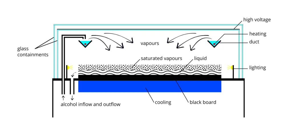
The fundamental principle behind them is the supersaturation of a vapor substance, a state in which the air, or any other gas, contains more vapour of that substance than it can hold in a stable equilibrium. An energetic charged particle (for example, an alpha or beta particle) interacts with the vapor mixture and creates a track of ions, which under supersaturation conditions act as condensation nuclei around which a mist-like trail of small droplets form if the gas mixture is at the point of condensation.
A diffusion-type cloud chamber. Alcohol (typically isopropanol) is evaporated by a heater in a duct in the upper part of the chamber. Cooling vapor descends to the black refrigerated plate, where it condenses. Due to the temperature gradient a layer of supersaturated vapor is formed above the bottom plate. In this region, radiation particles induce condensation and create cloud tracks. Source: wikipedia.org License: CC BY-SA 4.0
These droplets are visible as a “cloud” track that persist for several seconds while the droplets fall through the vapor. The condensation of the vapour on these nuclei allows visual identification of the trajectories of the particles, leading to a straightforward study of their properties. In Wilson’s original chamber the air inside the sealed device was saturated with water vapor, then a diaphragm was used to expand the air inside the chamber (adiabatic expansion), cooling the air and starting to condense water vapor. Hence the name expansion cloud chamber is used. The first antiparticle, the positron, the muon, and the first strange particle, the kaon, were also first identified using cloud chamber.
Diffusion Cloud Chamber
Although diffusion cloud chambers were never broadly used in nuclear and particle physics research, being easy to build an carry they still remain interesting educational instruments. A diffusion cloud chamber differs from the expansion cloud chamber in that it is continuously sensitized to radiation, and in that the bottom must be cooled to a rather low temperature, generally colder than −26 °C (−15 °F). Instead of water vapor, alcohol is used because of its lower freezing point. Nowadays, they are an easy way of learning about and visualising elementary particles and radiation.
Ionization and Track Information
It must be emphasized that drops that in these devices form tracks grow on ions created by the passage of ionising particles. Thus, this ionisation process must be analysed. Each type of particle interacts in a different way, therefore knowledge of this interaction, how different particles deposit energy in the matter and how much energy particles deposit, is fundamental for our understanding of the problem. For example charged particles with high energies can directly ionize atoms. Alpha particles are fairly massive and carry a double positive charge, so they tend to travel only a short distance and do not penetrate very far into tissue if at all. However alpha particles will deposit their energy over a smaller volume (possibly only a few cells if they enter a body) and cause more damage to those few cells. As a result, alpha particle leave short but significant trace in the chamber.
Beta particles (electrons) are much smaller than alpha particles. They carry a single negative charge. They are more penetrating than alpha particles. They can travel several meters but deposit less energy at any one point along their paths than alpha particles. Therefore, beta particles leave longer but less visible trace in the chamber.
If a magnetic field is applied across the cloud chamber, positively and negatively charged particles will curve in opposite directions, according to the Lorentz force law.
According to experimental data the specific ionisation dN/dx in cloud chambers, defined as the mean number of ions produced per unit of length by a passing particle, is well described to a first approximation both for electrons and for more massive particles by the Bethe equation.
Stopping Power – Bethe Formula
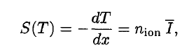
A convenient variable that describes the ionization properties of surrounding medium is the stopping power. The linear stopping power of material is defined as the ratio of the differential energy loss for the particle within the material to the corresponding differential path length:
,where T is the kinetic energy of the charged particle, nion is the number of electron-ion pairs formed per unit path length, and I denotes the average energy needed to ionize an atom in the medium. For charged particles, S increases as the particle velocity decreases. The classical expression that describes the specific energy loss is known as the Bethe formula. The non-relativistic formula was found by Hans Bethe in 1930. The relativistic version (see below) was found also by Hans Bethe in 1932.
In this expression, m is the rest mass of the electron, β equals to v/c, what expresses the particle’s velocity relative to the speed of light, γ is the Lorentz factor of the particle, Q equals to its charge, Z is the atomic number of the medium and n is the atoms density in the volume. For nonrelativistic particles (heavy charged particles are mostly nonrelativistic), dT/dx is dependent on 1/v2. This is can be explained by the greater time the charged particle spends in the negative field of the electron, when the velocity is low.
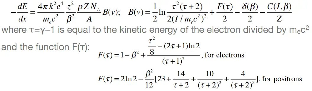
Nature of an interaction of a beta radiation with matter is different from the alpha radiation, despite the fact that beta particles are also charged particles. In comparison with alpha particles, beta particles have much lower mass and they reach mostly relativistic energies. Their mass is equal to the mass of the orbital electrons with which they are interacting and unlike the alpha particle a much larger fraction of its kinetic energy can be lost in a single interaction. Since the beta particles mostly reach relativistic energies, the nonrelativistic Bethe formula cannot be used. For high energy electrons an similar expression has also been derived by Bethe to describe the specific energy loss due to excitation and ionization (the “collisional losses”).
Modified Bethe formula for beta particles.
Moreover, beta particles can interact via electron-nuclear interaction (elastic scattering off nuclei), which can significantly change the direction of beta particle. Therefore their path is not so straightforward. The beta particles follow a very zig-zag path through absorbing material, this resulting path of particle is longer than the linear penetration (range) into the material.
Beta particles also differ from other heavy charged particles in the fraction of energy lost by radiative process known as the bremsstrahlung. From classical theory, when a charged particle is accelerated or decelerated, it must radiate energy and the deceleration radiation is known as the bremsstrahlung (“braking radiation”).
Cloud Chamber and Discovery of Positron
Positrons are positively charged (+1e), almost massless particles. Their rest mass equal to 9.109 × 10⁻³¹ kg (510.998 keV/c2) (approximately 1/1836 that of the proton).
Antielectrons were discovered by Paul Dirac and Carl D. Anderson in 1932 and named positrons. They studied cosmic-ray collisions via a cloud chamber – a particle detector in which moving electrons (or positrons) leave behind trails as they move through the gas. Source: wikipedia.org License: Public Domain
Like all elementary particles, electrons exhibit properties of both particles and waves: they can collide with other particles and can be diffracted like light. The original idea for antiparticles came from a relativistic wave equation developed in 1928 by the English scientist P. A. M. Dirac (1902-1984). He realised that his relativistic version of the Schrödinger wave equation for electrons predicted the possibility of antielectrons. These were discovered by Paul Dirac and Carl D. Anderson in 1932 and named positrons. They studied cosmic-ray collisions via a cloud chamber – a particle detector in which moving electrons (or positrons) leave behind trails as they move through the gas. Positron paths in a cloud chamber trace the same helical path as an electron but rotate in the opposite direction with respect to the magnetic field direction due to their having the same magnitude of charge-to-mass ratio but with opposite charge and, therefore, opposite signed charge-to-mass ratios. Although Dirac did not himself use the term antimatter, its use follows on naturally enough from antielectrons, antiprotons, etc.
Bubble Chamber
Bubble chambers are particle detectors, that are based on similar principle as cloud chambers. In the bubble chamber, the tracks of subatomic particles are revealed as trails of bubbles in a liquid heated to just below its boiling point, usually liquid hydrogen. Bubble chambers can be made physically larger than cloud chambers, and since they are filled with much-denser liquid material, they reveal the tracks of much more energetic particles. An energetic charged particle (for example, an alpha or beta particle) interacts with the liquid and the liquid enters into a superheated, metastable phase. Around the ionization track the liquid vaporizes, forming microscopic bubbles. Bubble density around a track is proportional to a particle’s energy loss.
It must be emphasized that bubbles that in these devices form tracks grow on ions created by the passage of ionising particles. Thus, this ionisation process must be analysed. Each type of particle interacts in a different way, therefore knowledge of this interaction, how different particles deposit energy in the matter and how much energy particles deposit, is fundamental for our understanding of the problem. For example charged particles with high energies can directly ionize atoms. Alpha particles are fairly massive and carry a double positive charge, so they tend to travel only a short distance and do not penetrate very far into tissue if at all. However alpha particles will deposit their energy over a smaller volume (possibly only a few cells if they enter a body) and cause more damage to those few cells. As a result, alpha particle leave short but significant trace in the chamber.
Beta particles (electrons) are much smaller than alpha particles. They carry a single negative charge. They are more penetrating than alpha particles. They can travel several meters but deposit less energy at any one point along their paths than alpha particles. Therefore, beta particles leave longer but less visible trace in the chamber.
If a magnetic field is applied across the cloud chamber, positively and negatively charged particles will curve in opposite directions, according to the Lorentz force law.
Robert Reed Burn, Introduction to Nuclear Reactor Operation, 1988.
U.S. Department of Energy, Nuclear Physics and Reactor Theory. DOE Fundamentals Handbook, Volume 1 and 2. January 1993.
Paul Reuss, Neutron Physics. EDP Sciences, 2008. ISBN: 978-2759800414.
See also:
Radiation Detection
We hope, this article, Cloud Chamber, helps you. If so, give us a like in the sidebar. Main purpose of this website is to help the public to learn some interesting and important information about radiation and dosimeters.
We hope, this article, Particle Detection – Particle Detectors, helps you. If so, give us a like in the sidebar. Main purpose of this website is to help the public to learn some interesting and important information about radiation and dosimeters.
The fundamental principle behind cloud chambers is the supersaturation of a vapor substance. Cloud Chamber – Principle of Operation
Alpha particles and electrons (deflected by a magnetic field) from a thorium rod in a cloud chamber. Source: wikipedia.org
Cloud chambers, also known as Wilson cloud chambers, are particle detectors, that were essential devices in early nuclear and particle physics research. Cloud chambers, one of the most simple instruments to study elementary particles, have been substituted by more modern detectors in actual research, but they still remain very interesting pedagogical apparatus.
Cloud Chamber – Principle of Operation
The fundamental principle behind them is the supersaturation of a vapor substance, a state in which the air, or any other gas, contains more vapour of that substance than it can hold in a stable equilibrium. An energetic charged particle (for example, an alpha or beta particle) interacts with the vapor mixture and creates a track of ions, which under supersaturation conditions act as condensation nuclei around which a mist-like trail of small droplets form if the gas mixture is at the point of condensation.
A diffusion-type cloud chamber. Alcohol (typically isopropanol) is evaporated by a heater in a duct in the upper part of the chamber. Cooling vapor descends to the black refrigerated plate, where it condenses. Due to the temperature gradient a layer of supersaturated vapor is formed above the bottom plate. In this region, radiation particles induce condensation and create cloud tracks. Source: wikipedia.org License: CC BY-SA 4.0
These droplets are visible as a “cloud” track that persist for several seconds while the droplets fall through the vapor. The condensation of the vapour on these nuclei allows visual identification of the trajectories of the particles, leading to a straightforward study of their properties. In Wilson’s original chamber the air inside the sealed device was saturated with water vapor, then a diaphragm was used to expand the air inside the chamber (adiabatic expansion), cooling the air and starting to condense water vapor. Hence the name expansion cloud chamber is used. The first antiparticle, the positron, the muon, and the first strange particle, the kaon, were also first identified using cloud chamber.
Robert Reed Burn, Introduction to Nuclear Reactor Operation, 1988.
U.S. Department of Energy, Nuclear Physics and Reactor Theory. DOE Fundamentals Handbook, Volume 1 and 2. January 1993.
Paul Reuss, Neutron Physics. EDP Sciences, 2008. ISBN: 978-2759800414.
See also:
Cloud Chamber
We hope, this article, Cloud Chamber – Principle of Operation, helps you. If so, give us a like in the sidebar. Main purpose of this website is to help the public to learn some interesting and important information about radiation and dosimeters.
A diffusion cloud chamber differs from the expansion cloud chamber in that it is continuously sensitized to radiation, and in that the bottom must be cooled to a rather low temperature, generally colder than −26 °C (−15 °F). Radiation Dosimetry
Alpha particles and electrons (deflected by a magnetic field) from a thorium rod in a cloud chamber. Source: wikipedia.org
Cloud chambers, also known as Wilson cloud chambers, are particle detectors, that were essential devices in early nuclear and particle physics research. Cloud chambers, one of the most simple instruments to study elementary particles, have been substituted by more modern detectors in actual research, but they still remain very interesting pedagogical apparatus.
Expansion Cloud Chamber
In Wilson’s original chamber the air inside the sealed device was saturated with water vapor, then a diaphragm was used to expand the air inside the chamber (adiabatic expansion), cooling the air and starting to condense water vapor. Hence the name expansion cloud chamber is used. The first antiparticle, the positron, the muon, and the first strange particle, the kaon, were also first identified using cloud chamber.
Diffusion Cloud Chamber
Although diffusion cloud chambers were never broadly used in nuclear and particle physics research, being easy to build an carry they still remain interesting educational instruments. A diffusion cloud chamber differs from the expansion cloud chamber in that it is continuously sensitized to radiation, and in that the bottom must be cooled to a rather low temperature, generally colder than −26 °C (−15 °F). Instead of water vapor, alcohol is used because of its lower freezing point. Nowadays, they are an easy way of learning about and visualising elementary particles and radiation.
Robert Reed Burn, Introduction to Nuclear Reactor Operation, 1988.
U.S. Department of Energy, Nuclear Physics and Reactor Theory. DOE Fundamentals Handbook, Volume 1 and 2. January 1993.
Paul Reuss, Neutron Physics. EDP Sciences, 2008. ISBN: 978-2759800414.
See also:
Cloud Chamber
We hope, this article, Diffusion Cloud Chamber and Expansion Cloud Chamber, helps you. If so, give us a like in the sidebar. Main purpose of this website is to help the public to learn some interesting and important information about radiation and dosimeters.
Positron paths in a cloud chamber trace the same helical path as an electron but rotate in the opposite direction with respect to the magnetic field direction due to their having the same magnitude of charge-to-mass ratio. Cloud Chamber and Discovery of Positron
Cloud chambers, also known as Wilson cloud chambers, are particle detectors, that were essential devices in early nuclear and particle physics research. Cloud chambers, one of the most simple instruments to study elementary particles, have been substituted by more modern detectors in actual research, but they still remain very interesting pedagogical apparatus.
Cloud Chamber and Discovery of Positron
Positrons are positively charged (+1e), almost massless particles. Their rest mass equal to 9.109 × 10⁻³¹ kg (510.998 keV/c2) (approximately 1/1836 that of the proton).
Antielectrons were discovered by Paul Dirac and Carl D. Anderson in 1932 and named positrons. They studied cosmic-ray collisions via a cloud chamber – a particle detector in which moving electrons (or positrons) leave behind trails as they move through the gas. Source: wikipedia.org License: Public Domain
Like all elementary particles, electrons exhibit properties of both particles and waves: they can collide with other particles and can be diffracted like light. The original idea for antiparticles came from a relativistic wave equation developed in 1928 by the English scientist P. A. M. Dirac (1902-1984). He realised that his relativistic version of the Schrödinger wave equation for electrons predicted the possibility of antielectrons. These were discovered by Paul Dirac and Carl D. Anderson in 1932 and named positrons. They studied cosmic-ray collisions via a cloud chamber – a particle detector in which moving electrons (or positrons) leave behind trails as they move through the gas. Positron paths in a cloud chamber trace the same helical path as an electron but rotate in the opposite direction with respect to the magnetic field direction due to their having the same magnitude of charge-to-mass ratio but with opposite charge and, therefore, opposite signed charge-to-mass ratios. Although Dirac did not himself use the term antimatter, its use follows on naturally enough from antielectrons, antiprotons, etc.
Robert Reed Burn, Introduction to Nuclear Reactor Operation, 1988.
U.S. Department of Energy, Nuclear Physics and Reactor Theory. DOE Fundamentals Handbook, Volume 1 and 2. January 1993.
Paul Reuss, Neutron Physics. EDP Sciences, 2008. ISBN: 978-2759800414.
See also:
Cloud Chamber
We hope, this article, Cloud Chamber and Discovery of Positron, helps you. If so, give us a like in the sidebar. Main purpose of this website is to help the public to learn some interesting and important information about radiation and dosimeters.
In the bubble chamber, the tracks of subatomic particles are revealed as trails of bubbles in a liquid heated to just below its boiling point, usually liquid hydrogen. Radiation Dosimetry
Alpha particles and electrons (deflected by a magnetic field) from a thorium rod in a cloud chamber. Source: wikipedia.org
Bubble chambers are particle detectors, that are based on similar principle as cloud chambers. In the bubble chamber, the tracks of subatomic particles are revealed as trails of bubbles in a liquid heated to just below its boiling point, usually liquid hydrogen. Bubble chambers can be made physically larger than cloud chambers, and since they are filled with much-denser liquid material, they reveal the tracks of much more energetic particles. An energetic charged particle (for example, an alpha or beta particle) interacts with the liquid and the liquid enters into a superheated, metastable phase. Around the ionization track the liquid vaporizes, forming microscopic bubbles. Bubble density around a track is proportional to a particle’s energy loss.
It must be emphasized that bubbles that in these devices form tracks grow on ions created by the passage of ionising particles. Thus, this ionisation process must be analysed. Each type of particle interacts in a different way, therefore knowledge of this interaction, how different particles deposit energy in the matter and how much energy particles deposit, is fundamental for our understanding of the problem. For example charged particles with high energies can directly ionize atoms. Alpha particles are fairly massive and carry a double positive charge, so they tend to travel only a short distance and do not penetrate very far into tissue if at all. However alpha particles will deposit their energy over a smaller volume (possibly only a few cells if they enter a body) and cause more damage to those few cells. As a result, alpha particle leave short but significant trace in the chamber.
Beta particles (electrons) are much smaller than alpha particles. They carry a single negative charge. They are more penetrating than alpha particles. They can travel several meters but deposit less energy at any one point along their paths than alpha particles. Therefore, beta particles leave longer but less visible trace in the chamber.
If a magnetic field is applied across the cloud chamber, positively and negatively charged particles will curve in opposite directions, according to the Lorentz force law.
Ionization and Track Information
It must be emphasized that drops that in these devices form tracks grow on ions created by the passage of ionising particles. Thus, this ionisation process must be analysed. Each type of particle interacts in a different way, therefore knowledge of this interaction, how different particles deposit energy in the matter and how much energy particles deposit, is fundamental for our understanding of the problem. For example charged particles with high energies can directly ionize atoms. Alpha particles are fairly massive and carry a double positive charge, so they tend to travel only a short distance and do not penetrate very far into tissue if at all. However alpha particles will deposit their energy over a smaller volume (possibly only a few cells if they enter a body) and cause more damage to those few cells. As a result, alpha particle leave short but significant trace in the chamber.
Beta particles (electrons) are much smaller than alpha particles. They carry a single negative charge. They are more penetrating than alpha particles. They can travel several meters but deposit less energy at any one point along their paths than alpha particles. Therefore, beta particles leave longer but less visible trace in the chamber.
If a magnetic field is applied across the cloud chamber, positively and negatively charged particles will curve in opposite directions, according to the Lorentz force law.
According to experimental data the specific ionisation dN/dx in cloud chambers, defined as the mean number of ions produced per unit of length by a passing particle, is well described to a first approximation both for electrons and for more massive particles by the Bethe equation.
Stopping Power – Bethe Formula
A convenient variable that describes the ionization properties of surrounding medium is the stopping power. The linear stopping power of material is defined as the ratio of the differential energy loss for the particle within the material to the corresponding differential path length:
,where T is the kinetic energy of the charged particle, nion is the number of electron-ion pairs formed per unit path length, and I denotes the average energy needed to ionize an atom in the medium. For charged particles, S increases as the particle velocity decreases. The classical expression that describes the specific energy loss is known as the Bethe formula. The non-relativistic formula was found by Hans Bethe in 1930. The relativistic version (see below) was found also by Hans Bethe in 1932.
In this expression, m is the rest mass of the electron, β equals to v/c, what expresses the particle’s velocity relative to the speed of light, γ is the Lorentz factor of the particle, Q equals to its charge, Z is the atomic number of the medium and n is the atoms density in the volume. For nonrelativistic particles (heavy charged particles are mostly nonrelativistic), dT/dx is dependent on 1/v2. This is can be explained by the greater time the charged particle spends in the negative field of the electron, when the velocity is low.
Nature of an interaction of a beta radiation with matter is different from the alpha radiation, despite the fact that beta particles are also charged particles. In comparison with alpha particles, beta particles have much lower mass and they reach mostly relativistic energies. Their mass is equal to the mass of the orbital electrons with which they are interacting and unlike the alpha particle a much larger fraction of its kinetic energy can be lost in a single interaction. Since the beta particles mostly reach relativistic energies, the nonrelativistic Bethe formula cannot be used. For high energy electrons an similar expression has also been derived by Bethe to describe the specific energy loss due to excitation and ionization (the “collisional losses”).
Modified Bethe formula for beta particles.
Moreover, beta particles can interact via electron-nuclear interaction (elastic scattering off nuclei), which can significantly change the direction of beta particle. Therefore their path is not so straightforward. The beta particles follow a very zig-zag path through absorbing material, this resulting path of particle is longer than the linear penetration (range) into the material.
Beta particles also differ from other heavy charged particles in the fraction of energy lost by radiative process known as the bremsstrahlung. From classical theory, when a charged particle is accelerated or decelerated, it must radiate energy and the deceleration radiation is known as the bremsstrahlung (“braking radiation”).
Robert Reed Burn, Introduction to Nuclear Reactor Operation, 1988.
U.S. Department of Energy, Nuclear Physics and Reactor Theory. DOE Fundamentals Handbook, Volume 1 and 2. January 1993.
Paul Reuss, Neutron Physics. EDP Sciences, 2008. ISBN: 978-2759800414.
See also:
Cloud Chamber
We hope, this article, Bubble Chamber, helps you. If so, give us a like in the sidebar. Main purpose of this website is to help the public to learn some interesting and important information about radiation and dosimeters.
Nuclear instrumentations are usually categorized as: Excore Nuclear Instrumentation and Incore Nuclear Instrumentation. Both systems are based on detection of neutrons. Radiation Dosimetry
In nuclear reactors, the thermal power produced by nuclear fissions is proportional to neutron flux level. Therefore, from reactor safety point of view, it is of the highest importance to measure and control the neutron flux and the spatial distribution of the neutron flux in the reactor correctly and by appropriate instrumentation. For this purpose, various nuclear instrumentations are installed. These measurements are usually performed outside the reactor core, but there are also measurements performed from inside the core. Therefore, nuclear instrumentations are usually categorized as:
Excore Nuclear Instrumentation. The neutron flux is usually measured by excore neutron detectors installed outside the core. These detectors belong to so called the excore nuclear instrumentation system (NIS). Since the neutron flux covers a wide range (about 12 decades), three ranges of instrumentation are used to obtain accurate flux level measurements:
Incore Nuclear Instrumentation. The incore nuclear instrumentation system measures neutron flux distribution and temperatures in the reactor core. The purposes of the incore instrumentation system are to provide detailed information on neutron flux distribution and fuel assembly outlet temperatures at selected core locations. The incore instrumentation system includes:
Both systems are based on detection of neutrons. The neutron flux is usually measured by excore neutron detectors installed outside the core. These detectors belong to so called the excore nuclear instrumentation system (NIS). The neutron flux and its distribution within the core is usually measure by an incore system, which is installed inside the reactor. Although the nuclear instrumentation system provides prompt response on neutron flux changes and it is irreplaceable system, it must be calibrated. The accurate thermal power of the reactor can be measured only by methods based on energy balance of primary circuit or energy balance of secondary circuit. These methods provide accurate reactor power, but these methods are insufficient for safety systems. Signal inputs to these calculations are, for example, the hot leg temperature or the flow rate through the feedwater system and these signals change very slowly with neutron power changes. In other word, the thermal power measured by calorimetrical methods is accurate, while the nuclear power measured by excore neutron detectors is the only system capable of fast reactivity excursion detection.
Reaction Rate – Proportionality between Neutron Flux and Thermal Power
Knowledge of the neutron flux(the total path length of all the neutrons in a cubic centimeter in a second) and the macroscopic cross sections (the probability of having an interaction per centimeter path length) allows us to compute the rate of interactions (e.g. rate of fission reactions). This reaction rate (the number of interactions taking place in that cubic centimeter in one second) is then given by multiplying them together:
To determine the thermal power, we have to focus on the fission reaction rate. For simplicity let assume that the fissionable material is uniformly distributed in the reactor. In this case, the macroscopic cross-sections are independent of position. Multiplying the fission reaction rate per unit volume (RR = Ф . Σ) by the total volume of the core (V) gives us the total number of reactions occurring in the reactor core per unit time. But we also know the amount of energy released per one fission reaction to be about 200 MeV/fission. Now, it is possible to determine the rate of energy release (power) due to the fission reaction. It is given by following equation:
P = RR . Er . V = Ф . Σf . Er . V = Ф . NU235 . σf235 . Er . V
where:
P – reactor power (MeV.s-1)
Ф – neutron flux (neutrons.cm-2.s-1)
σ – microscopic cross section (cm2)
N – atomic number density (atoms.cm-3)
Er – the average recoverable energy per fission (MeV / fission)
Robert Reed Burn, Introduction to Nuclear Reactor Operation, 1988.
U.S. Department of Energy, Nuclear Physics and Reactor Theory. DOE Fundamentals Handbook, Volume 1 and 2. January 1993.
Paul Reuss, Neutron Physics. EDP Sciences, 2008. ISBN: 978-2759800414.
See also:
Nuclear Reactor
We hope, this article, Nuclear Instrumentation, helps you. If so, give us a like in the sidebar. Main purpose of this website is to help the public to learn some interesting and important information about radiation and dosimeters.
The neutron flux is usually measured by excore neutron detectors installed outside the core. These detectors belong to so called the excore nuclear instrumentation system (NIS). Radiation Dosimetry
The neutron flux is usually measured by excore neutron detectors installed outside the core. These detectors belong to so called the excore nuclear instrumentation system (NIS). The excore nuclear instrumentation system monitors the power level of the reactor by detecting neutron leakage from the reactor core. The excore nuclear instrumentation system usually consists of three separate overlapping ranges of excore instrumentation, which monitor the neutron flux level generated in the core from a few counts per second up to approximately 1015 neutrons/cm2 /sec (corresponds to approximately 200 percent of nominal power). Since the neutron flux covers a wide range (about 12 decades), three ranges of instrumentation are used to obtain accurate flux level measurements:
These excore detectors are usually located in instrument wells in the primary shield (concrete shield) adjacent to the reactor vessel. The system provides indication, control, and alarm signals for reactor operation and protection. Therefore the excore nuclear instrumentation system is considered a safety related system, because it provides inputs to the reactor protection system during startup and power operation. This system is of the highest importance for reactor protection system, because changes in the neutron flux can be almost promptly recognized only via this system.
The primary function of the excore nuclear instrumentation system is to protect the reactor core from overpower by monitoring the neutron flux and generating appropriate alarms and reactor trips to shutdown the reactor when required. Each range of instrumentation (source, intermediate, and power) provides the necessary overpower reactor trip protection (high neutron flux reactor trip) required during operation in that range.
Detection of Neutrons using Gaseous Ionization Detectors
Since the neutrons are electrically neutral particles, they are mainly subject to strong nuclear forces but not to electric forces. Therefore neutrons are not directly ionizing and they have usually to be converted into charged particles before they can be detected. Generally every type of neutron detector must be equipped with converter (to convert neutron radiation to common detectable radiation) and one of the conventional radiation detectors (scintillation detector, gaseous detector, semiconductor detector, etc.).
Ionization chambers are often used as the charged particle detection device. For example, if the inner surface of the ionization chamber is coated with a thin coat of boron, the (n,alpha) reaction can take place. Most of (n,alpha) reactions of thermal neutrons are 10B(n,alpha)7Li reactions accompanied by 0.48 MeV gamma emission.
Moreover, isotope boron-10 has high (n,alpha) reaction cross-section along the entire neutron energy spectrum. The alpha particle causes ionization within the chamber, and ejected electrons cause further secondary ionizations.
Another method for detecting neutrons using an ionization chamber is to use the gas boron trifluoride (BF3) instead of air in the chamber. The incoming neutrons produce alpha particles when they react with the boron atoms in the detector gas. Either method may be used to detect neutrons in nuclear reactor. It must be noted, BF3 counters are usually operated in the proportional region.
Source Range Detectors
The source range detectors monitor neutron flux (reactor power) at the lowest shutdown levels and provide indication, alarms, and reactor trips. Source range instrumentation usually consists of two or four source range channels, each with its own separate detector, cable run, and electronic circuitry. The detectors utilized are usually high-sensitivity boron-triflouride (BF3) proportional counters. In general, proportional counters are capable of particle identification and energy measurement (spectroscopy). The pulse height reflects the energy deposited by the incident radiation in the detector gas. As such, it is possible to distinguish the larger pulses produced by alpha particles (produced by (n,alpha) reactions) from the smaller pulses produced by beta particles or gamma rays.
These BF3 detectors produce a pulse rate output proportional to the thermal neutron flux seen at the detector. These channels are typically used over a counting range of 0.1 to 106 counts per second, but vary based on reactor design. These excore detectors are usually located in instrument wells in the primary shield (concrete shield) adjacent to the reactor vessel.
The source range instrumentation monitors and indicates the neutron flux level of the reactor core and the rate by which the neutron flux changes during a reactor shutdown and the initial phase of start-up. They are very important for monitoring of subcriticality during fuel reload, when subcritical multiplication takes place. The neutron flux is indicated in counts per second (cps). The rate of change of the neutron population is indicated as startup rate (SUR), which is defined as the number of factors of ten that power changes in one minute. Therefore the units of SUR are powers of ten per minute, or decades per minute (dpm).
There are two principal problems in the source range instrumentation:
Discrimination. During the reactor shutdown and the initial phase of start-up, it is required to distinguish the relatively small number of pulses produced by neutrons from the large number of pulses produced by gamma radiation. Thus gamma discrimination is of particular interest during shutdown after the reactor core reaches significant level of fuel burnup. This condition produces a high gamma field and a low neutron flux around the detector. Proportional counters allow for discrimination but they must be calibrated. The discriminator excludes passage of pulses that are less than a predetermined level. The function of the discriminator is to exclude noise and gamma pulses that are lower in magnitude than neutron pulses (alpha pulses respectively). Many power plants have found it necessary to place source range proportional counters in lead shielding to reduce gamma radiation at the detectors. This increases the low end sensitivity of the detector, and it may extend the detector life.
Dead Time. This instrument can indicate up to a maximum neutron count rate of 106 cps. Higher count rates are influenced by phenomenon known as dead-time. The dead-time is the period during which the detector is busy and cannot accept and process pulses. This phenomenon can have serious consequences, since dead-time distorts outputs at high activities or high dose rates.
There are some power plants that have made provisions for moving the source range detectors from their operating positions to a position of reduced neutron flux level, once the flux level increases above the source range.
Special Reference: Standard Review Plan for the Review of Safety Analysis Reports for Nuclear Power Plants: LWR Edition. NUREG-0800, US NRC.
Source Range – Reactor Safety
As was written, the excore nuclear instrumentation system is considered a safety related system, because it provides inputs to the reactor protection system. The source range neutron flux trip provides the core protection for reactivity accidents in MODE 2 (reactor startup). For example, the source range neutron flux trip ensures that protection is provided against an uncontrolled RCCA bank rod withdrawal accident from a subcritical condition during startup. It also provides protection for boron dilution accident and control rod ejection events.
During refueling, source range detectors also ensure monitoring of reactor subcriticality. They are also equipped with an alarm, that may serve as a containment evacuation signal if the neutron flux exceeds a preset value. This alarm alerts the control room operators and personnel in containment of a positive reactivity addition to the reactor during shutdown conditions.
Intermediate Range Detectors
The intermediate range detectors monitor neutron flux (reactor power) at the intermediate flux level. They also provide indication, alarms, and reactor trip signals. Their range is from the upper part of the source range through the power range (cover a span of eight decades). The design of this instrument is chosen to provide overlap between the source range channels and partial or full span of the power range instruments. Intermediate range instrumentation usually consists of two or four channels, each with its own separate detector, cable run, and electronic circuitry. The detectors utilized are usually boron-lined or boron gas-filled compensated ionization chambers or fission chambers. Their accuracy usually does not achieve the accuracy of the power range instrumentation operating in a much narrower range.
The source range instrumentation monitors and indicates the neutron flux level of the reactor core and the rate by which the neutron flux changes during entire phase of reactor start-up and power operation. The neutron flux is indicated in percentage of rated power. The rate of change of the neutron population is indicated as startup rate (SUR), which is defined as the number of factors of ten that power changes in one minute. Therefore the units of SUR are powers of ten per minute, or decades per minute (dpm). High startup rate on either channel may initiate a protective action.
Intermediate Range – Reactor Safety
As was written, the excore nuclear instrumentation system is considered a safety related system, because it provides inputs to the reactor protection system. The intermediate range neutron flux trip provides the core protection against an uncontrolled RCCA bank rod withdrawal accident from a subcritical condition during startup. This trip function provides redundant protection to the power range neutron flux – low setpoint. It also provides redundant protection to the source range trip function for boron dilution accident and control rod ejection events.
Compensated Ionization Chambers
Compensated Ionization Chamber Source: U.S. Department of Energy, Instrumentation and Control. DOE Fundamentals Handbook, Volume 2 of 2. June 1992.
The ionization chamber, also known as the ion chamber, is electrical device that detects various types of ionizing radiation. The voltage of detector is adjusted so that the conditions correspond to the ionization region. The voltage is not high enough to produce gas amplification (secondary ionization). Ionization chambers are preferred for high radiation dose rates because they have no “dead time”, a phenomenon which affects the accuracy of the Geiger-Mueller tube at high dose rates.
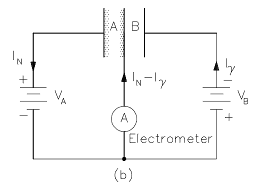
The compensated ion chamber is utilized in the intermediate range because the current output is proportional to the relatively stable neutron flux, and it compensates for signals from gamma flux. The compensated ion chamber consist of two detectors in one case. The outer chamber is coated on the inside with boron-10, while the inner chamber is uncoated. The coated chamber is sensitive to both gamma rays and neutrons, while the uncoated chamber is sensitive only to gamma rays. By connecting the two chambers in a proper way, the net electrical output from the detector will be the current due to neutrons only.
To achieve the proper amount of gamma compensation, the voltages between these two sets of electrodes must be balanced. The consequences of operating with an overcompensated or undercompensated chamber are important. If the voltage in the compensation chamber is too high, the detector is overcompensated and some neutron current, as well as all of the gamma current, is blocked, and indicated power is lower than actual core power. If the compensating voltage is too low, undercompensation will occur. At high power, gamma flux is relatively small compared to neutron flux, and the effects of improper compensation may not be noticed. It is extremely important, however, that the chamber be properly compensated during reactor startup and shutdown.
See also: U.S. Department of Energy, Instrumentation and Control. DOE Fundamentals Handbook, Volume 2 of 2. June 1992.
Fission Chamber – Wide Range Detectors
Fission chambers are ionization detectors used to detect neutrons. Fission chambers may be used as the intermediate range detectors to monitor neutron flux (reactor power) at the intermediate flux level. They also provide indication, alarms, and reactor trip signals. The design of this instrument is chosen to provide overlap between the source range channels and full span of the power range instruments.
In general, the ionization chamber, also known as the ion chamber, is electrical device that detects various types of ionizing radiation. The voltage of detector is adjusted so that the conditions correspond to the ionization region. The voltage is not high enough to produce gas amplification (secondary ionization). Ionization chambers are preferred for high radiation dose rates because they have no “dead time”, a phenomenon which affects the accuracy of the Geiger-Mueller tube at high dose rates. Moreover, in the ionization region, an increase in voltage does not cause a substantial increase in the number of ion-pairs collected. The number of ion-pairs collected by the electrodes is equal to the number of ion-pairs produced by the incident radiation, and is dependent on the type and energy of the particles or rays in the incident radiation.
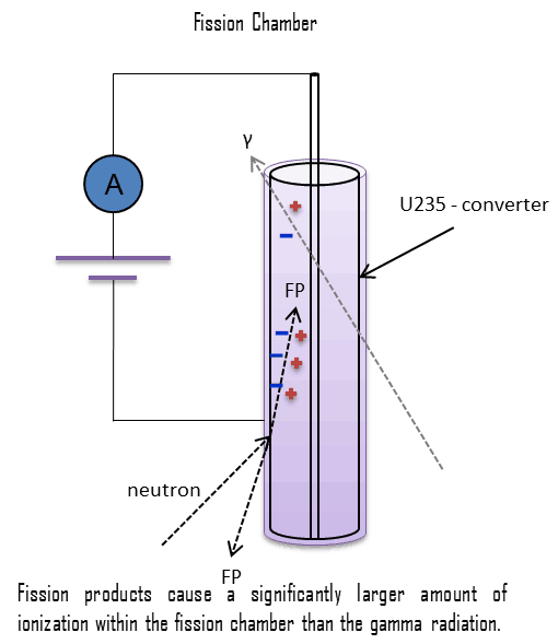
In case of fission chambers, the chamber is coated with a thin layer of highly enriched uranium-235 to detect neutrons. Neutrons are not directly ionizing and they have usually to be converted into charged particles before they can be detected. A thermal neutron will cause an atom of uranium-235 to fission, with the two fission fragments produced having a high kinetic energy and causing ionization of the argon gas within the detector. One advantage of using uranium-235 coating rather than boron-10 is that the fission fragments have a much higher energy than the alpha particle from a boron reaction. Moreover, the fission fragments resulting from the interaction of neutrons with the coating cause a significantly larger amount of ionization within the fission chamber than the gamma radiation incident on the detector. This results in the neutron generated charge pulses being significantly larger than the gamma pulses. Pulse size discrimination circuitry can then be used to block out the unwanted gamma pulses. Therefore fission chambers are very sensitive to neutron flux and this allows the fission chambers to operate in higher gamma fields than an uncompensated ion chamber with boron lining.
Fission chambers are often used as current indicating devices and pulse devices depending on the neutron flux level. In the pulse mode, fission chambers are especially useful, due to the very large pulse size difference between neutrons and gamma rays. When power is high in the intermediate range or in the power range (i.e. in a high level mixed gamma and neutron flux), fission chambers can be operated in Campbelling mode (also known as “fluctuation mode” or “mean square voltage mode”) to provide reliable and precise neutron related measurements. The Campbelling technique eliminates the gamma contribution. Because of the fission chamber’s dual use, it is often used in “wide range” channels in nuclear instrumentation systems.
Power Range Detectors
Power range detectors are key nuclear instrumentation system for power operation. They monitor neutron flux (reactor power) from zero to about 120% of full rated power along with indication of the axial and radial distribution of that power. They also provide indication, alarms, and reactor trip signals. As neutron flux level increase into the power range, gamma compensation is not a major concern because gamma rays do not contribute much to the total ionization (about 0.1% at 100% power). Therefore, the power range instrumentation usually consists of four uncompensated ionization chambers, each with its own separate detector, cable run, and electronic circuitry. The ionization chamber, also known as the ion chamber, is electrical device that detects various types of ionizing radiation. The voltage of detector is adjusted so that the conditions correspond to the ionization region. The voltage is not high enough to produce gas amplification (secondary ionization). Ionization chambers are preferred for high radiation dose rates because they have no “dead time”, a phenomenon which affects the accuracy of the Geiger-Mueller tube at high dose rates. The detector consists of a single cylindrical chamber whose operation is identical to that of the boron lined chamber of the compensated ion chamber. This uncompensated chamber is sensitive to both gamma rays and neutrons. However, in the power range of operation, the neutron flux level is many times greater than the gamma flux, and therefore, no gamma compensation is required.
All four channels are physically and functionally identical. Each power range channel employs an upper and a lower uncompensated ion chamber detector (tandem detector) which allows for measurement of axial flux difference. Each channel also monitors a “quadrant” of the core. An upper detector and a lower detector are mounted inside the same instrument well. The outputs of both detectors (upper and lower) are combined to produce a channel total power signal. The eight detector outputs (four upper detectors and four lower detectors) are compared to each other to provide power distribution information (AFD and QPTR) to the reactor operator.
The axial flux difference is defined as the difference in normalized flux signals (AFD) between the top and bottom halves of a two section excore neutron detector, will decrease.
AFD is defined as:
AFD or ΔI = Itop – Ibottom
where Itop and Ibottom are expressed as a fraction of rated thermal power.
QPTR is defined as:
The ratio of the maximum upper excore detector calibrated output to the average of the upper excore detector calibrated outputs, or the ratio of the maximum lower excore detector calibrated output to the average of the lower excore detector calibrated outputs, whichever is greater.
The power range instrumentation monitors and indicates the neutron flux level of the reactor core and the rate by which the neutron flux changes during a power operation and standard load follow operation. The neutron flux is indicated as percentage of rated power. The rate of change of the neutron population is indicated as startup rate (SUR), which is defined as the number of factors of ten that power changes in one minute. Therefore the units of SUR are powers of ten per minute, or decades per minute (dpm).
Although the nuclear instrumentation system provides prompt response on neutron flux changes and it is irreplaceable system, it must be calibrated. Power range channels are calibrated to indicate percent rated thermal power by a secondary heat balance (calorimetric). The accurate thermal power of the reactor can be measured only by methods based on energy balance of primary circuit or energy balance of secondary circuit.
Special Reference: Standard Review Plan for the Review of Safety Analysis Reports for Nuclear Power Plants: LWR Edition. NUREG-0800, US NRC.
Neutron Flux and Fuel Burnup
In a power reactor over a relatively short period of time (days or weeks), the atomic number density of the fuel atoms remains relatively constant. Therefore in this short period, also the average neutron flux remains constant, when reactor is operated at a constant power level. On the other hand, the atomic number densities of fissile isotopes over a period of months decrease due to the fuel burnup and therefore also the macroscopic cross-sections decrease. This results is slow increase in the neutron flux in order to keep the desired power level. Therefore, the excore nuclear instrumentation system must be periodically calibrated.
Power Range – Reactor Safety
As was written, the excore nuclear instrumentation system is considered a safety related system, because it provides inputs to the reactor protection system. The power range neutron flux trip provides the core protection for many power excursion accidents in MODE 1 (power operation). Examples of protective action signals provided by the power range include:
The Power Range Neutron Flux (Low – Setpoint). A reactor trip will occur if power level exceeds the preset value (for example 25%) on two of four channels, and the trip is not blocked.
The Power Range Neutron Flux (High – Setpoint). A reactor trip will occur if power level exceeds the preset value (for example 109%) on two of four channels to protect the core from an overpower condition and to protect from a positive reactivity excursion leading to DNB during power operations. This trip cannot be blocked.
Rate Trips. If the rate of change of reactor power exceeds a preset value in either the positive or negative direction, a reactor trip will occur.
High Positive Rate trip ensures that protection is provided against rapid increases in neutron flux that are characteristic of an RCCA drive rod housing rupture and the accompanying ejection of the RCCA.
High Negative Rate trip ensures that protection is provided for multiple rod drop accidents. At high power levels, a multiple rod drop accident could cause local flux peaking that would result in a nonconservative local DNBR.
Robert Reed Burn, Introduction to Nuclear Reactor Operation, 1988.
U.S. Department of Energy, Nuclear Physics and Reactor Theory. DOE Fundamentals Handbook, Volume 1 and 2. January 1993.
Paul Reuss, Neutron Physics. EDP Sciences, 2008. ISBN: 978-2759800414.
See also:
Nuclear Instrumentation
We hope, this article, Excore Nuclear Instrumentation, helps you. If so, give us a like in the sidebar. Main purpose of this website is to help the public to learn some interesting and important information about radiation and dosimeters.
The incore nuclear instrumentation system measures neutron flux distribution and temperatures in the reactor core. Incore Nuclear Instrumentation
The incore nuclear instrumentation system measures neutron flux distribution and temperatures in the reactor core. The purposes of the incore instrumentation system are to provide detailed information on neutron flux distribution and fuel assembly outlet temperatures at selected core locations. The incore instrumentation system provides data acquisition and usually performs no protective or plant operational control functions.
The incore neutron monitoring system consists of incore detectors with sufficient sensitivity to permit measurement of localized neutron flux distribution variations within the reactor core. It must be noted, in power reactor cores the flux distribution, and also the power distribution is significantly influenced by many factors. Therefore, the temperature in an operating reactor varies from point to point within the system. As a consequence, there is always one fuel rod and one local volume, that are hotter than all the rest. In order to limit these hot places the peak power limits must be introduced. The peak power limits are associated with a boiling crisis and with the conditions which could cause fuel pellet melt. The incore neutron flux monitoring system provides detailed information on neutron flux distribution and thus the margins to these peak power limits.
The incore neutron flux monitoring system usually utilize:
miniature fission chambers
self-powered neutron detectors
These movable flux detectors, that are usually placed into the instrumentation tube of a fuel assembly, they can monitor the entire length of selected fuel assemblies to provide an extremely accurate, three-dimensional map of the neutron flux distribution. Using these data, neutron flux reconstruction can be performed also in the rest of the reactor core. The data obtained from the incore neutron flux monitoring system is usually (depending on certain reactor design) used to:
This data can be used to determine the power distribution in the core at any time during the fuel cycle. The monitored power distribution is used to verify that the following power distribution hot channel factors are in compliance with technical specification limits:
The Heat Flux Hot Channel Factor – FQ(z), which is defined as: The ratio of the maximum local linear power density, where there is a minimal margin to limiting fuel temperature (during AOOs), to the average local linear power density in the core.
The Nuclear Enthalpy Rise Hot Channel Factor – FNΔH, which is defined as: The ratio of the integral of linear power along the fuel rod on which minimum departure from nucleate boiling ratio occurs (during AOOs), to the average fuel rod power in the core.
This data can be used to determine fuel burnup, and isotopic fuel inventories in the core at any time during the fuel cycle.
This data can be used to calibrate the excore power range nuclear instruments for axial flux difference (AFD)
This data can be used to verify that the quadrant power tilt ratio (QPTR) meets the technical specification limit.
The data will also provide trends of core conditions so that corrective action can be taken before a condition becomes excessive.
The incore neutron temperature monitoring system consists of incore thermocouples, that are positioned at preselected locations to measure fuel assembly coolant outlet temperature for use in monitoring the core radial power sharing and coolant enthalpy distribution. It must be noted coolant outlet temperatures are more or less influenced by lateral flow mixing and for some reactor designs this system has another purpose such as safety functions monitoring. This data (coolant outlet temperatures) may be (depending on certain reactor design) used to:
Provide the operators with indications of inadequate core cooling conditions during emergency situations (e.g. core overtemperature)
Provide information about temperature rise in the fuel assembly. This may indicate a serious core condition (e.g. channel blockage) and should be investigated.
Provide inputs to the subcooling margin monitors
Provide inputs to plant computer computational applications which use core-exit temperatures to determine fuel assembly enthalpy rises and limited power distribution information.
Self-Powered Neutron Detectors (SPND) are neutron detectors, that are being widely used in reactors to monitor neutron flux due to its adaptability for in-core severe environment. SPNDs may be a part of the incore neutron flux monitoring system, which provides detailed information on neutron flux distribution and thus the margins to these peak power limits. These detectors use the basic radioactive decay process of its neutron activation material to produce an output signal. As the name implies, SPNDs do not require an external voltage source to create a voltage potential in the detector. Instead, a current is produced in the detector as the result of neutron activation and subsequent beta decay of the detector itself. Because of the emission of these beta particles (electrons), the wire becomes more and more positively charged. The positive potential of the wire causes a current to flow in resistor, R. The electron current from beta decay can be measured directly with an ammeter.
There are two main advantages of the self-powered neutron detector:
Very little instrumentation is required, usually only a millivoltmeter or an ammeter
The emitter material has a much greater lifetime than boron or uranium-235 lining used in fission chambers.
On the other hand, there are also disadvantages, one is associated with the fact that currents even at full power operation are very low. Therefore, SPNDs are unable to provide with information about flux distribution at low power operation (10% and less). The main disadvantage of the self-powered neutron detector is that the emitter material decays with a characteristic half-life, which determines the response time of the detector. Depending on the response time, these detectors are broadly classified as:
Prompt response detectors. The prompt response detectors as Cobalt and Inconel are used in reactor protection and regulation applications.
Delayed response detectors. The delayed response detectors like Vanadium and Rhodium are being widely used for Flux Mapping System (FMS).
The typical SPND is a coaxial cable consisting of:
Emitter. An inner electrode, which is made from a material that absorbs a neutron and undergoes radioactive decay by emitting an electron (beta decay). The emitter is usually made of rhodium and is used to produce electrons.
Insulation. The emitter is surrounded by insulation, which is usually made of aluminum oxide.
Collector. The metal walls of the detector encase these parts and serve as a collector for the. electrons that are produced.- The collector is attached to ground potential,
Self-powered neutron detectors are usually placed into the instrumentation tube of a fuel assembly, they can monitor the entire length of selected fuel assemblies to provide an extremely accurate, three-dimensional map of the neutron flux distribution. Using these data, neutron flux reconstruction can be performed also in the rest of the reactor core.
Typical materials used for the emitter are cobalt, cadmium, rhodium, and vanadium. These materials should be used because they possess relatively high melting temperatures, relatively high cross sections to thermal neutrons and are compatible with the SPND manufacturing process.
Special Reference: William H. Todt, Sr. CHARACTERISTICS OF SELF-POWERED NEUTRON DETECTORS USED IN POWER REACTORS. Imaging and Sensing Technology Corporation. New York.
Rhodium Emitter – Rhodium-based SPND
One of possible materials is rhodium as the emitter. A SPND with a rhodium emitter has a relatively high sensitivity, high burn-up rate, perturbs the local power density and has a (two-fold) delayed signal. Rhodium-based detector is the beta-current type of self-powered detector, which uses the following activation reaction to produce a current that can be measured.
1n + 103Rh → 104Rh → 104Pd + β
As can be seen, a neutron captured by rhodium-103 causes a rhodium-103 atom to become a radioactive rhodium-104 atom. The rhodium-104 then decays into palladium-104 plus a beta particle (electron). The beta particle has enough energy to pass through the insulator and reach the collector. The half-life of activated rhodium-104 is 42.3 seconds, which delays the emission of the charged particle. Rhodium based detector uses this production of beta particles (electrons) to create a current that is proportional to the number of neutrons captured by the emitter, which is also proportional to local reactor power density. A portion of the detector’s current flow is due to gamma rays. In order to compensate for this erroneous signal, a background correction is performed via background detector, which consists of the same components as the detector, except the rhodium is removed.
Rhodium-103 has a capture cross-section of 133 barns for thermal neutrons and a resonance at 1.25 eV. This reaction leads to production of 104Rh with T1/2 = 42 sec which is beta radioactive. It must be noted about 11 barns belong to reaction in which an isomer 104mRh is produced (with T1/2 = 4.4 min).
The following characteristics are typical when used in thermal power reactor (e.g. PWR).
The rhodium burnup rate is 0.39% per month in a thermal neutron flux of 1013n/cm2/sec.
92% of the signal has a half-life of 42 seconds.
8% of the signal has a half-life of 4.4 minutes.
The beta emission has an energy of 2.44 MeV.
Vanadium Emitter – Vanadium-based SPND
A SPND with a vanadium emitter has a relatively low sensitivity, low burn-up rate, with minimal perturbation of the local power density and has a very long delayed signal. Vanadium-based detector is the beta-current type of self-powered detector, which uses the following activation reaction to produce a current that can be measured.
1n + 51V → 52V → 52Cr + β
Vanadium-51 has a capture cross-section of 4.9 barns for thermal neutrons without resonances. This reaction leads to production of 52V with T1/2 = 3.74 min which is beta radioactive.
The following characteristics are typical when used in thermal power reactor (e.g. PWR).
The vanadium burnup rate is 0.012% per month in a thermal neutron flux of 1013n/cm2/sec.
99% of the signal has a half-life of 3.8 minutes.
1% of the signal is prompt.
The subsequent beta emission has an energy of 2.6 MeV.
Robert Reed Burn, Introduction to Nuclear Reactor Operation, 1988.
U.S. Department of Energy, Nuclear Physics and Reactor Theory. DOE Fundamentals Handbook, Volume 1 and 2. January 1993.
Paul Reuss, Neutron Physics. EDP Sciences, 2008. ISBN: 978-2759800414.
See also:
Nuclear Instrumentation
We hope, this article, Incore Nuclear Instrumentation, helps you. If so, give us a like in the sidebar. Main purpose of this website is to help the public to learn some interesting and important information about radiation and dosimeters.
Source range detectors monitor neutron flux (reactor power) at the lowest shutdown levels and provide indication, alarms, and reactor trips. Source range instrumentation usually consists of two or four source range channels. Radiation Dosimetry
Source range detectors monitor neutron flux (reactor power) at the lowest shutdown levels and provide indication, alarms, and reactor trips. Source range instrumentation usually consists of two or four source range channels, each with its own separate detector, cable run, and electronic circuitry. The detectors utilized are usually high-sensitivity boron-triflouride (BF3) proportional counters. In general, proportional counters are capable of particle identification and energy measurement (spectroscopy). The pulse height reflects the energy deposited by the incident radiation in the detector gas. As such, it is possible to distinguish the larger pulses produced by alpha particles (produced by (n,alpha) reactions) from the smaller pulses produced by beta particles or gamma rays.
These BF3 detectors produce a pulse rate output proportional to the thermal neutron flux seen at the detector. These channels are typically used over a counting range of 0.1 to 106 counts per second, but vary based on reactor design. These excore detectors are usually located in instrument wells in the primary shield (concrete shield) adjacent to the reactor vessel.
Detection of Neutrons using Gaseous Ionization Detectors
Since the neutrons are electrically neutral particles, they are mainly subject to strong nuclear forces but not to electric forces. Therefore neutrons are not directly ionizing and they have usually to be converted into charged particles before they can be detected. Generally every type of neutron detector must be equipped with converter (to convert neutron radiation to common detectable radiation) and one of the conventional radiation detectors (scintillation detector, gaseous detector, semiconductor detector, etc.).
Ionization chambers are often used as the charged particle detection device. For example, if the inner surface of the ionization chamber is coated with a thin coat of boron, the (n,alpha) reaction can take place. Most of (n,alpha) reactions of thermal neutrons are 10B(n,alpha)7Li reactions accompanied by 0.48 MeV gamma emission.
Moreover, isotope boron-10 has high (n,alpha) reaction cross-section along the entire neutron energy spectrum. The alpha particle causes ionization within the chamber, and ejected electrons cause further secondary ionizations.
Another method for detecting neutrons using an ionization chamber is to use the gas boron trifluoride (BF3) instead of air in the chamber. The incoming neutrons produce alpha particles when they react with the boron atoms in the detector gas. Either method may be used to detect neutrons in nuclear reactor. It must be noted, BF3 counters are usually operated in the proportional region.
The source range instrumentation monitors and indicates the neutron flux level of the reactor core and the rate by which the neutron flux changes during a reactor shutdown and the initial phase of start-up. They are very important for monitoring of subcriticality during fuel reload, when subcritical multiplication takes place. The neutron flux is indicated in counts per second (cps). The rate of change of the neutron population is indicated as startup rate (SUR), which is defined as the number of factors of ten that power changes in one minute. Therefore the units of SUR are powers of ten per minute, or decades per minute (dpm).
There are two principal problems in the source range instrumentation:
Discrimination. During the reactor shutdown and the initial phase of start-up, it is required to distinguish the relatively small number of pulses produced by neutrons from the large number of pulses produced by gamma radiation. Thus gamma discrimination is of particular interest during shutdown after the reactor core reaches significant level of fuel burnup. This condition produces a high gamma field and a low neutron flux around the detector. Proportional counters allow for discrimination but they must be calibrated. The discriminator excludes passage of pulses that are less than a predetermined level. The function of the discriminator is to exclude noise and gamma pulses that are lower in magnitude than neutron pulses (alpha pulses respectively). Many power plants have found it necessary to place source range proportional counters in lead shielding to reduce gamma radiation at the detectors. This increases the low end sensitivity of the detector, and it may extend the detector life.
Dead Time. This instrument can indicate up to a maximum neutron count rate of 106 cps. Higher count rates are influenced by phenomenon known as dead-time. The dead-time is the period during which the detector is busy and cannot accept and process pulses. This phenomenon can have serious consequences, since dead-time distorts outputs at high activities or high dose rates.
There are some power plants that have made provisions for moving the source range detectors from their operating positions to a position of reduced neutron flux level, once the flux level increases above the source range.
Special Reference: Standard Review Plan for the Review of Safety Analysis Reports for Nuclear Power Plants: LWR Edition. NUREG-0800, US NRC.
Source Range – Reactor Safety
As was written, the excore nuclear instrumentation system is considered a safety related system, because it provides inputs to the reactor protection system. The source range neutron flux trip provides the core protection for reactivity accidents in MODE 2 (reactor startup). For example, the source range neutron flux trip ensures that protection is provided against an uncontrolled RCCA bank rod withdrawal accident from a subcritical condition during startup. It also provides protection for boron dilution accident and control rod ejection events.
During refueling, source range detectors also ensure monitoring of reactor subcriticality. They are also equipped with an alarm, that may serve as a containment evacuation signal if the neutron flux exceeds a preset value. This alarm alerts the control room operators and personnel in containment of a positive reactivity addition to the reactor during shutdown conditions.
Robert Reed Burn, Introduction to Nuclear Reactor Operation, 1988.
U.S. Department of Energy, Nuclear Physics and Reactor Theory. DOE Fundamentals Handbook, Volume 1 and 2. January 1993.
Paul Reuss, Neutron Physics. EDP Sciences, 2008. ISBN: 978-2759800414.
See also:
Excore Instrumentation
We hope, this article, Source Range Detector, helps you. If so, give us a like in the sidebar. Main purpose of this website is to help the public to learn some interesting and important information about radiation and dosimeters.